

Factory service manual for the Bomag BW 216 D-4 and BW 216 PD-4 single drum soil compactors, the PD being the padfoot drum version. Covers the Deutz TCD 2013 L04 2V engine (119 kW at 2200 rpm) with EMR3 electronic management, including the flash code system for engine faults. You get real workshop numbers: travel circuit pressure tests (high pressure limitation 400 + 26 bar, charge pressure 26 bar), vibration circuit measurements (start up pressure 345 + 26 bar), steering pressure 175 + 26 bar, plus flushing and bleeding procedures for the hydraulics. Mechanical chapters walk through drum removal, change-over weights, the oscillating articulated joint, and cab glass replacement. Wiring and hydraulic diagrams are included with a proper guide to reading them.
What's Inside This Bomag BW 216 D-4, BW 216 PD-4 Manual
| System | Pages | Key Topics |
|---|---|---|
| General | 1-32 | Bw 216 D-4 / Bw 216 Pd-4, Single Drum Roller, Safety Regulations, Important Notes, Transport Work with Cranes and Lifting Tackle, Electric Shock!, Behaviour in Case of Faults |
| Technical Data | 33-38 | Dimensions, Weights, Travel Speeds, Vibration Data, Engine Data, Filling Capacities |
| Maintenance and Connection Overview | 39-52 | General Notes on Maintenance, Fuels and Lubricants, Engine Oil, Fuels, Coolant, Anti-Freeze Agent, Hydraulic Oil, Oil for Drive Axle |
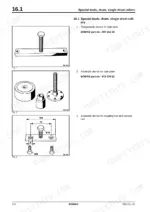
| Tests and Adjustments | 53-66 | Special Tools, Pressure Tests in the Travel Circuit, Checking / Adjusting the Vibrator Shaft Speeds, Pressure Measurements in the Vibration Circuit, Switch on Vibration with High or Low Frequency., Nominal Value, Evaluation of Test |
| Flushing and Bleeding | 67-102 | Special Tools for Flushing, Flushing - General, Changing a Component, Chips (Abrasion) in the Oil, Before Flushing, Servicing the Flushing Filter Kit, Flushing the Drum Drive |
| Electrics | 103-174 | Understanding Circuit Diagrams, Structure, Potential Cross References, Relay Cross Reference, Current Paths, Component Cross References, Designation of Components in the Wiring Diagram |
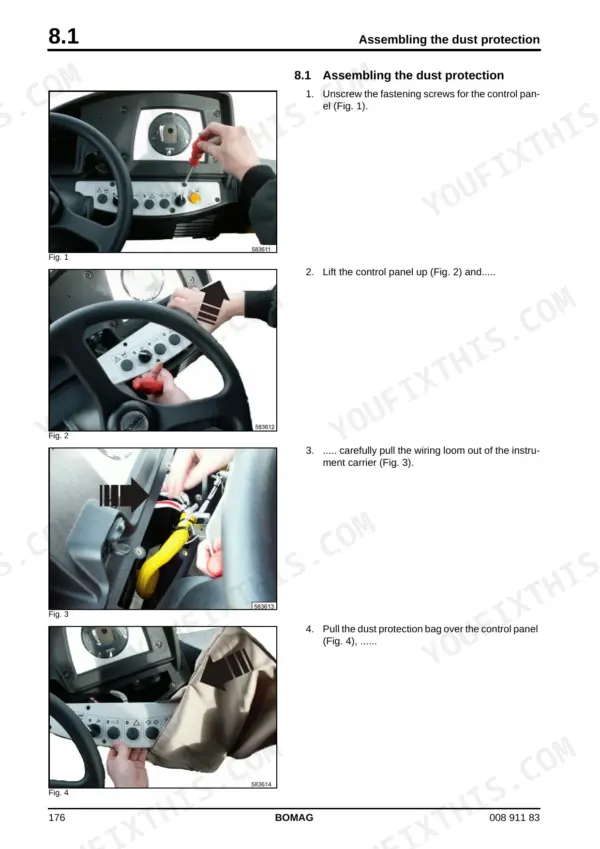
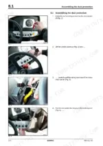
| Dust Protection | 175-180 | Assembling the Dust Protection |
| Engine Electrics (Deutz EMR III) | 181-310 | EMR3 System Components, Engine Control Unit, Pin Assignment of Engine Control EDC16 / EMR3, Rotary Speed Sensor for Camshaft, Speed Sensor, B114, Rotary Speed Sensor for Crankshaft, B130 |
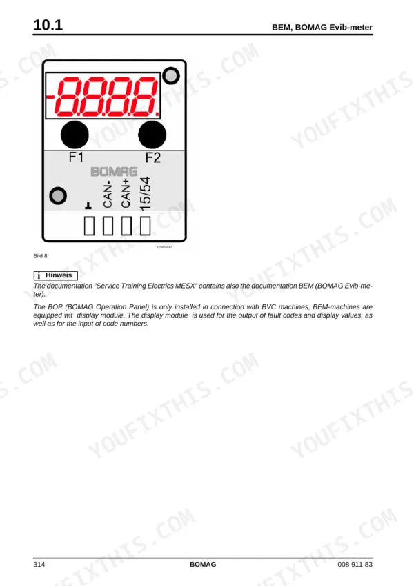
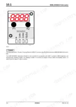
| Electronic Modules | 311-394 | Bem, BOMAG Evib-Meter, Electrics Module A68, Electric Module K04, Heating/Air Conditioning Control |
| Speedometer Module | 395-398 | Description of Function, Teaching the Module |
| Service Training | 399-462 | |
| Engine | 463-520 | Diesel Engine, Engine Description TCD 2013, 4 and 6 Cylinder, Lubrication Oil Circuit TCD 2012 / 2013, Coolant Circuit TCD 2012 / 2013, Fuel System TCD 2012 / 2013, Exhaust Gas Recirculation TCD 2012 / 2013, Engine Problems |
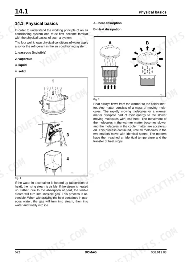
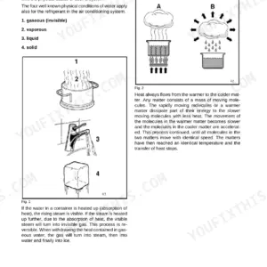
| Air Conditioning System | 521-564 | Physical Basics, A - Heat Absorption, Refrigerant R134a, Compressor Oil / Refrigeration Oil, Working Principle of the Air Conditioning System, Monitoring Devices, Description of Components |
| Replacing the Cab Window Panes | 565-574 | Auxiliary Materials, Safety Gloves, Removing and Installing the Window Pane |
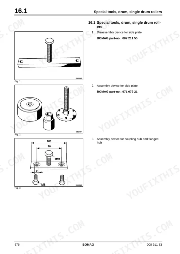
| Drum | 575-630 | Special Tools, Single Drum Rollers, Removing and Installing the Drum, Repairing the Drum, Removing the Travel Motor, Dismantling, Assembling the Change- Over Weights, Dismantling the Change-Over Weight |
| Oscillating Articulated Joint | 631-654 | Dismantling the Oscillating Articulated Joint, Assembling the Oscillating Articulated Joint |
| Suppliers Documentation - Travel Pump | 655-810 | |
| Suppliers Documentation - Vibration Pump | 811-880 | |
| Suppliers Documentation - Travel Motor | 881-962 | |
| Suppliers Documentation - Vibration Motor | 963-986 | |
| Suppliers Documentation - Axle | 987-1136 | Drum Reduction Gear, Steering Valve |
| Circuit Diagrams | 1137-1216 | Hydraulic Diagram 581 202 06, Wiring Diagram 582 702 14, Wiring Diagram 582 702 30 |
Quick Reference Specifications
| Specification | Value | Page |
|---|---|---|
| Engine | Deutz TCD 2013 L04 2V, 119 kW at 2200 rpm | p. 34 |
| Operating weight (CECE) with ROPS and cabin, BW 216 D-4 | 15700 kg | p. 34 |
| Operating weight (CECE) with ROPS and cabin, BW 216 PD-4 | 16200 kg | p. 34 |
| Travel speeds (4 ranges) | 0-4 / 0-5 / 0-7 / 0-11 km/h | p. 34 |
| Travel pump high pressure limitation | 400 + 26 bar | p. 35 |
| Travel pump charge pressure (high idle) | 26 bar | p. 35 |
| Max. steering pressure | 175 + 26 bar | p. 36 |
| Fuel capacity | 340 litres | p. 35 |
| Engine oil capacity | 15 litres | p. 35 |
| Hydraulic oil capacity | 60 litres, HV 46 (ISO) | p. 35 |
| Valve clearance (intake / exhaust) | 0,4 mm / 0,6 mm | p. 35 |
Bomag BW 216 D-4, BW 216 PD-4 Common Problems This Manual Covers
Roller shuts down intermittently or will not restart, with a relay or contact fault in the shutdown circuit
Work the Electrics chapter first: it teaches how to read the circuit diagrams, relay cross references and current paths so you can trace the shutdown relay and its contacts on wiring diagram 582 702 14 instead of swapping parts blind.
Manual Section: Electrics - Understanding circuit diagrams / Wiring diagram 582 702 14 p. 104Overheating or coolant temperature warnings, often traced to the cooling blower belt slipping or breaking
The Engine chapter covers the coolant circuit for the TCD 2012/2013 and an Engine problems section for diagnosis. Verify belt condition and coolant level (16 l capacity, p.35), and check the anti-freeze mix per the Maintenance and Connection Overview chapter.
Manual Section: Engine - Coolant circuit TCD 2012 / 2013, Engine problems p. 470Weak compaction, no high or low frequency vibration, or vibration that fades when the oil warms up
Section 5.5 (p.63) gives pressure measurements in the vibration circuit for both frequencies: start up 345 + 26 bar, roughly 100 bar running. Compare against nominal values, evaluate per the test table, then check vibrator shaft speeds before opening the drum.
Manual Section: Tests and Adjustments 5.5 - Pressure measurements in the vibration circuit (p.63) p. 63Metal chips found in the hydraulic oil after a pump or motor failure in the travel or vibration circuit
Do not just bolt in a new unit. The Flushing and Bleeding chapter covers the flushing filter kit, flushing after changing a component, handling chips (abrasion) in the oil, and flushing the drum drive so debris does not destroy the replacement.
Manual Section: Flushing and Bleeding - Chips (abrasion) in the oil, Flushing the drum drive p. 73Frequently Asked Questions
The engine warning lamp is flashing and the roller dies or will not stay running. Where do I start?
This machine uses Deutz EMR3 electronic engine management, and faults come out as flashing codes on the lamp, not plain text. Section 9.18 (p.213) explains how system faults are indicated by flashing code, and chapter 9 (p.181-310) covers every EMR3 component with pin assignments for the EDC16/EMR3 control unit, the crankshaft speed sensor B130 and the camshaft sensor B114. Intermittent shutdowns on these machines are often relay or contact problems in the shutdown circuit, so check the wiring diagram chapter (582 702 14 / 582 702 30) before condemning the ECU. p. 213
Vibration is weak or dead. How do I tell if it is the pump, the motor, or something cheap?
Put gauges on it before pulling anything. Section 5.5 (p.63) gives the vibration circuit pressure measurements: start up pressure should hit 345 + 26 bar (the + 26 is the book's charge pressure notation), then settle around 100 bar in operation. The manual also covers checking and adjusting the vibrator shaft speeds with nominal values and how to evaluate the test. Full pressure but no shake points at the drum end, and the Drum chapter covers removing the travel motor and dismantling the change-over weights. p. 63
One side is sluggish or the machine crawls. What are the travel circuit test values?
Section 5.3 (p.60) walks the travel circuit pressure tests. The travel pump specs are max flow 163.65 l/min, high pressure limitation 400 + 26 bar, and charge pressure 26 bar (p.35). Low charge pressure is the usual quiet killer, so check that first along with the hydraulic filter. If a pump or motor has failed, the Flushing and Bleeding chapter is not optional: it covers flushing after changing a component and dealing with chips (abrasion) in the oil so the new part does not eat the same debris. p. 60
What are the fluids and capacities so I can stock a full service?
From the technical data (p.35): fuel tank 340 l, engine oil 15 l, coolant 16 l, hydraulic system 60 l of HV 46 (ISO viscosity 46 mm2/s at 40 C, p.43). The Maintenance and Connection Overview chapter details engine oil grades, fuels, coolant and anti-freeze, and the oil for the drive axle. Valve clearance for the TCD 2013 is 0,4 mm intake / 0,6 mm exhaust (p.35 and p.497), and combustion air filter service is section 13.17 (p.493) with the vacuum switch indicator described on p.210. p. 35
Does this manual cover the drum rebuild and the articulated joint, or just the engine?
Both ends of the machine. The Drum chapter lists the special tools for single drum rollers, then covers removing and installing the drum, repairing it, pulling the travel motor, and dismantling and assembling the change-over weights that switch vibration amplitude. A separate chapter covers dismantling and assembling the oscillating articulated joint, which takes a beating on a 15700-16200 kg machine. Suppliers documentation sections cover the travel pump, vibration pump, both motors, and the axle with its drum reduction gear and steering valve. p. 575
Reviews
There are no reviews yet.