

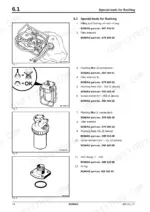
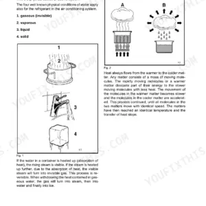
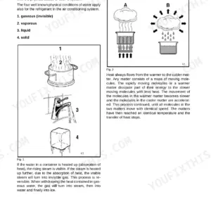
Factory service manual for the BOMAG BW 190 AD-4 AM and BW 203 AD-4 AM tandem vibratory rollers with Asphalt Manager. This is the workshop book, not the operator's leaflet: pressure tests for the travel and vibration circuits with nominal values (travel pump 440 bar high pressure limitation, charge pressure 25 +3/-1 bar), angle sensor adjustment for the travel control lever, flushing and bleeding procedures after a component change, and removal/installation of drums and exciter units. Covers the Deutz BF4M 2012 C engine (98 kW at 2300 rpm), ESX control fault codes, the BAM and A03/A68/A71 electronics modules, wiring and hydraulic diagrams, air conditioning, frame weld repair, and a full Asphalt Manager service training section.
What's Inside This Bomag BW 190 AD-4 AM, BW 203 AD-4 AM Manual
| System | Pages | Key Topics |
|---|---|---|
| General | 1-28 | Bw 190 Ad-4 Am, Bw 203 Ad-4 Am, Tandem Vibratory Roller, Asphalt Manager, Safety Regulations, Important Notes, Transport Work with Cranes and Lifting Tackle |
| Technical Data | 29-36 | Dimensions, Weights, Travel Speeds, Vibration Data, Noise Value, Filling Capacities |
| Maintenance and Connection Overview | 37-48 | General Notes on Maintenance, Fuels and Lubricants, Engine Oil, Oil Viscosity, Regular Lubrication Oil Changes, Oil Quality, Lubrication Oil Change Intervals |
| Tests and Adjustments | 49-72 | Special Tools, Adjusting the Angle Sensor, Checking the Rotation Speeds, Pressure Tests in the Travel Circuit, Read High Pressure and Charge Pressure Gauges., Nominal Value, Evaluation of Test |
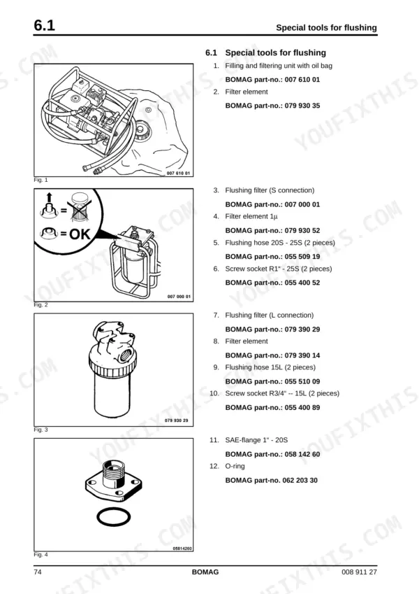
| Flushing and Bleeding | 73-102 | Special Tools for Flushing, Flushing - General, Changing a Component, Chips (Abrasion) in the Oil, Before Flushing, Servicing the Flushing Filter Kit, Flushing the Front Drum Drive |
| Fundamental Electrics | 103-164 | Understanding Circuit Diagrams, Structure, Potential Cross References, Relay Cross Reference, Current Paths, Component Cross References, Terminal Designations in Wiring Diagram |
| Special Tools, Electrics | 165-174 | Measuring Equipment, Electric Test Case, BOMAG Part-No.: 057 505 70, Multimeter, BOMAG Part-No.: 057 509 91, BOMAG Part-No.: 079 900 53, BOMAG Part-No.: 079 900 54 |
| Electronic Modules | 175-298 | Bam, Electrics Module A03, Electrics Module A68, Electrics Module A71, Heating/Air Conditioning Control |
| Service Training | 299-430 | Asphalt Manager |
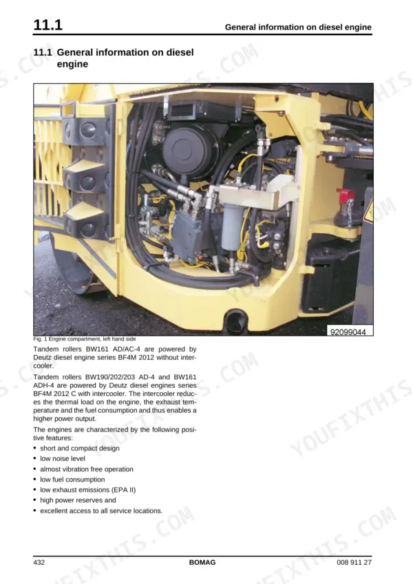
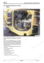
| Engine | 431-512 | General Information on Diesel Engine, Service Side, Starter Side, Lubrication Oil Circuit, Coolant Circuit, Coolant Temperature Switch, Removal |
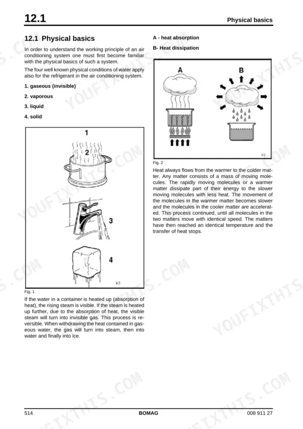
| Air Conditioning System | 513-556 | Physical Basics, A - Heat Absorption, Refrigerant R134a, Compressor Oil / Refrigeration Oil, Working Principle of the Air Conditioning System, Monitoring Devices, Description of Components |
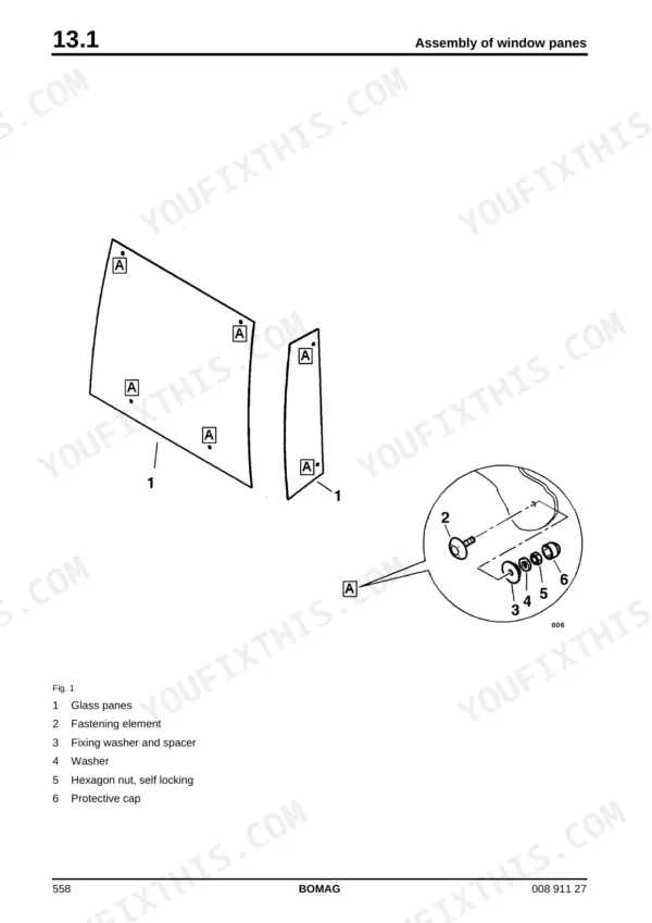
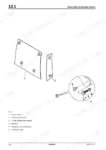
| Cab Windows, Frame, Travel Control Cable | 557-580 | Replacing the Cab Window Panes, Auxiliary Materials, Safety Gloves, Removing and Installing the Window Pane, Frame Cracks in Front Frame, Repair Overview for Welding the Frame, Welding the Frame |
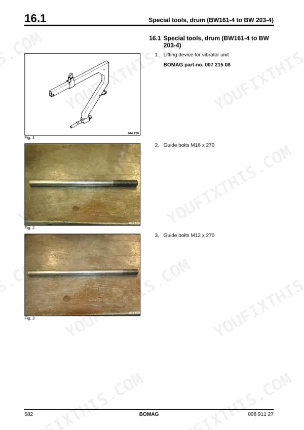
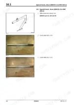
| Drum | 581-694 | Special Tools, Drum (BW161-4 to BW 203-4), BW161 with Bonfiglioli Reduction Gear, Removing and Installing the Drum, Removing the Drum, Danger of Squashing!, AD/AP Disassembling, Assembling the Exciter Unit, Dismantling |
| Oscillating Articulated Joint and Vibration Valve | 695-722 | Repair Overview Oscillating Articulated Joint, Crab Walk Cylinder, Assembling the Oscillating Articulated Joint, Install and Connect the Crab Walk Cylinder., Install and Connect Both Steering Cylinders., Assemble the Water Hoses., Install the Battery. |
| Suppliers Documentation - Travel Pump | 723-802 | |
| Suppliers Documentation - Vibration Pump | 803-860 | |
| Suppliers Documentation - Vibration Motors | 861-902 | |
| Suppliers Documentation - Drum Reduction Gear | 903-956 | |
| Suppliers Documentation - Drum Drive | 957-1060 | |
| Circuit Diagrams | 1061-1210 | Hydraulic Diagram 920 100 53, Hydraulic Diagram 920 100 62, Wiring Diagram 920 100 04, Wiring Diagram 920 100 05, Wiring Diagram 920 100 06, Wiring Diagram 920 100 07 |
| Supplement to Circuit Diagram | 1211-1234 | Control Elements, Old Design, New Design, Cabin, Monitoring Module A15, Machine |
Quick Reference Specifications
| Specification | Value | Page |
|---|---|---|
| Engine | Deutz BF4M 2012 C, 98 kW at 2300 rpm | p. 30 |
| Operating weight (CECE), BW 190 AD-4 AM | 11880 kg | p. 30 |
| Operating weight (CECE), BW 203 AD-4 AM | 12600 kg | p. 32 |
| Travel pump high pressure limitation | 440 bar | p. 34 |
| Travel pump charge pressure (high idle) | 25 +3/-1 bar | p. 34 |
| Max. steering pressure | 205 ± 15 bar | p. 35 |
| Fuel tank capacity | 200 litres | p. 31 |
| Engine oil capacity | 9.5 litres | p. 31 |
| Hydraulic oil capacity | 60 litres, HV 46 (ISO) | p. 31 |
| Water tank (sprinkler system) | 1000 litres | p. 31 |
| Valve clearance (intake / exhaust) | 0,3 mm / 0,5 mm | p. 495 |
Bomag BW 190 AD-4 AM, BW 203 AD-4 AM Common Problems This Manual Covers
Machine creeps, pulls to one side or has no drive at all
Run the travel circuit pressure tests in section 5.4 with the high pressure and charge pressure gauges, compare against the nominal values (440 bar limitation, 25 +3/-1 bar charge), then evaluate per the test tables before condemning the pump.
Manual Section: Tests and Adjustments, section 5.4 - Pressure tests in the travel circuit p. 59Travel lever response is off or the machine does not reach set speed
The angle sensor on the travel control lever drifts out of adjustment. Section 5.2 walks through adjusting the angle sensor and checking the rotation speeds, so the lever position matches actual pump output again without guesswork.
Manual Section: Tests and Adjustments, section 5.2 - Adjusting the angle sensor p. 50Vibration weak, slow to start, or dead on one drum
Test the vibration circuit per section 5.7: start up pressure should hit 360 +/- 20 bar, settling near 100 bar on the mat. Off spec points to the pump or motor; the Drum chapter then covers exciter unit disassembly and assembly.
Manual Section: Tests and Adjustments, section 5.7 - Vibration circuit pressure tests p. 66Debris found in hydraulic oil after a component failure
Do not just swap the part. The Flushing and Bleeding chapter covers the flushing filter kit, what to do before flushing, and flushing the drum drives, so chips from the failed unit do not destroy the replacement within a hundred hours.
Manual Section: Flushing and Bleeding - Flushing after changing a component p. 79Frequently Asked Questions
Does this manual explain the ESX fault codes and the Asphalt Manager electronics?
Yes. The Electronic Modules chapter documents the fault codes of the ESX control, plus the BAM and electrics modules A03, A68 and A71. On top of that there is a dedicated Service Training section on the Asphalt Manager, which controls compaction power independently from the driver. If the display throws a code or the automatic amplitude adjustment acts up, this is where you diagnose it instead of swapping parts blind. p. 180
My roller drives weak or the vibration is down. Can I test the hydraulics with this manual?
Yes, and with real numbers. Travel circuit pressure tests are in section 5.4, vibration circuit tests in section 5.7, each with nominal values and an evaluation of the result: travel pump high pressure limitation 440 bar, charge pressure at high idle 25 +3/-1 bar, vibration start up pressure 360 +/- 20 bar with roughly 100 bar in operation depending on the mat. Hook up the gauges, compare, and you know whether it is the pump, a motor or just contamination. p. 59
What does it say about flushing the hydraulic system after a pump or motor failure?
There is a full Flushing and Bleeding chapter. It covers when flushing is mandatory (changing a component, chips or abrasion found in the oil), the special flushing filter kit and how to service it, and step by step flushing of the drum drives. Skip this after a pump grenade and the debris takes out the new unit too. Hydraulic oil spec is HV 46, 60 litre system capacity. p. 79
Are the wiring and hydraulic diagrams included, and can a normal mechanic read them?
Both are in. Hydraulic diagrams 920 100 53 and 920 100 62, wiring diagrams 920 100 04 through 07, plus a supplement covering old and new design control elements and the A15 monitoring module. The Fundamental Electrics chapter teaches you to read them: current paths, potential cross references, relay cross references and terminal designations. That matters because these machines exist in old and new design variants and the diagrams differ. p. 103
Does it cover routine service specs like oil, filters and valve clearance?
Yes. Engine oil capacity 9.5 l with viscosity and quality tables, fuel 200 l, hydraulic oil HV 46 at 60 l, water tank 1000 l for the sprinkler. Valve clearance on the Deutz BF4M 2012 C is 0,3 mm intake / 0,5 mm exhaust. Combustion air filter check, cleaning and change is section 11.38. Given how many filters these machines eat at 500 and 1000 hour services, having the intervals and specs in one place pays for itself. p. 31

Reviews
There are no reviews yet.