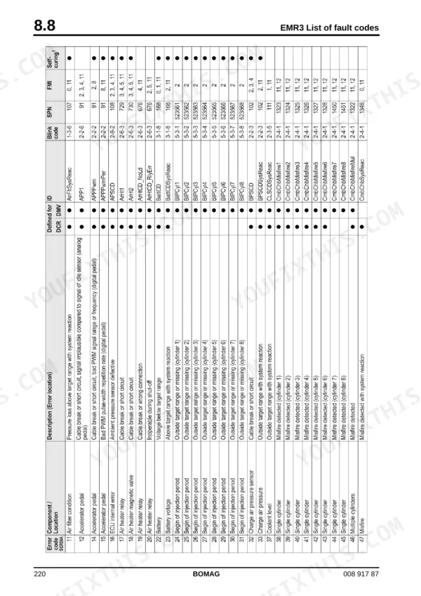
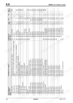
An hour from now you could be at the pressure test bar with this Bomag MPH 122-2 service manual PDF open on the screen: 658 factory pages for the soil stabilizer and asphalt recycler, OEM 008 917 87. Circuit diagrams close the book, from hydraulic diagram 593 301 24 through the machine wiring to separate electric, hydraulic, pneumatic and heating schematics for the bitumen metering system. Fault tracing on the Deutz TCD 2015 V6 runs from flashing codes through SERDIA and CAN-bus diagnostics to the full EMR3 fault code list, and the A4VG56 travel pump and A4VG180 rotor pump each get their own troubleshooting sections. Crank the starter one minute at most, then let it cool 30 minutes; never heat oils past 160 degrees C. Misdiagnose a rotor pump and you pay for the rebuild twice. Pay once here, and a bookmarked, text-searchable copy stays with your machine for good.
What's Inside This Manual
| System | Pages | Key Topics |
|---|
| General | 7-30 | Introduction, Safety Regulations, General Repair Instructions |
| Bomag Stabilizer / Recycler | 31-36 | Universal Rotor, Rotor Speed, Cutting Chisels, Cross-Slope, Rotor Hood Side Plates, All-Wheel Drive |
| Technical Data | 37-42 | Operating Weight, Track Radius, Travel Speed, Engine Type, Tire Size, Filling Capacities |
| Maintenance | 43-56 | Fuels and Lubricants, Table of Fuels and Lubricants, Running-In Instructions, Maintenance Table |
| E-Plan Wiring Diagrams | 57-72 | Understanding Wiring Diagrams, Circuit Symbols in the Circuit Diagram, Identification of Switch Blocks in the Wiring Diagram |
| Electrics | 73-120 | Designation of Components in the Wiring Diagram, Terminal Designations in Wiring Diagram, Batteries, Battery Service, Checking the Main Battery Switch, Starting with Jump Wires |
| Electronic Control | 121-200 | Training |
| Engine Electrics | 201-326 | Engine Control Unit |
| Engine | 327-378 | Diesel Engine, Engine Description Tcd 2015 V 6 Cylinder, Lubrication Oil Circuit Tcd 2015, Coolant Circuit Tcd 2015, Fuel Circuit Tcd 2015, Injection System Tcd 2015 |
| Air Conditioning System | 379-422 | Physical Basics, Refrigerant R134a, Compressor Oil / Refrigeration Oil, Working Principle of the Air Conditioning System, Monitoring Devices, Components |
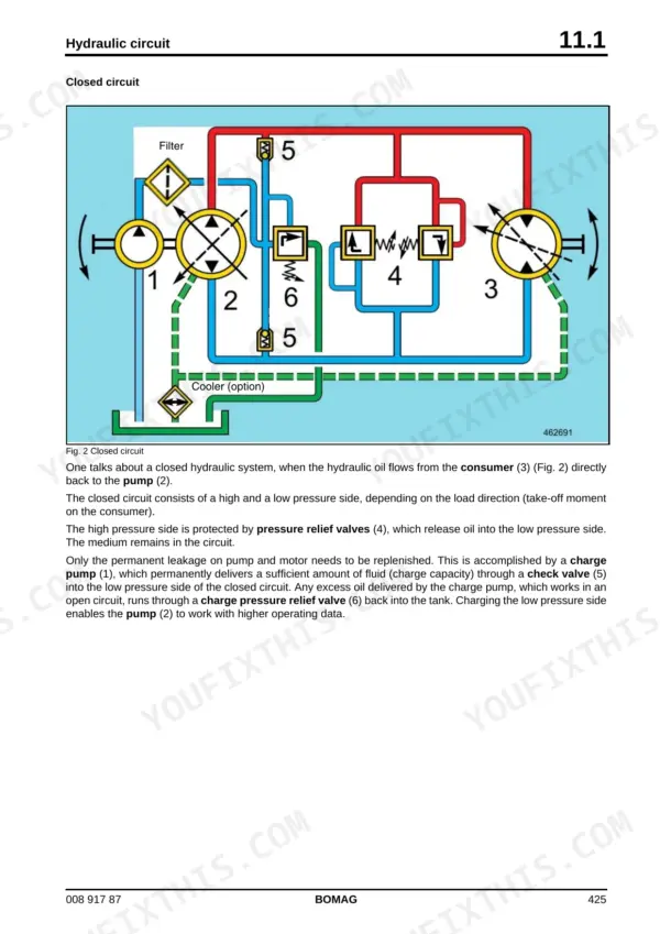
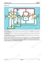
| Hydraulics | 423-500 | Hydraulic Circuit, List of Components, Pumps on Diesel Engine, Pressure Test Bar, Travel Pump A4VG56 Ep, Rotor Pump, A4VG180 Ep, Axial Piston Swash Plate Principle |
| Water Injection | 501-516 | Water Dosing System, Water Dosing System Nozzle Change, Water Sprinkler System, Maintenance in the Event of Frost |
| Bitumen Dosing System | 517-548 | Control Elements |
| Circuit Diagrams | 549-658 | Hydraulic Diagram 593 301 24, Wiring Diagram 42, Bitumen Metering System Electrics, Bitumen Metering System Hydraulics, Bitumen Metering System Pneumatics |
Quick Reference Specifications
| Specification | Value | Page |
|---|
| Maximum temperature for heating oils | 160 °C | p. 13 |
| Starter operation time | 1 minute | p. 16 |
| Tightening torque for M4 (8.8) | 3 Nm | p. 26 |
| Tightening torque for M4 (10.9) | 5 Nm | p. 26 |
| Main relay switch-off delay | 10 seconds | p. 202 |
| Footpedal (setpoint) 1 output voltage | 5 V | p. 204 |
| Oil pressure sensor tightening torque | 20 Nm | p. 295 |
| Tightening torque for coolant temperature sensor | 22±2 Nm | p. 302 |
| Maximum air pressure for blowing out cooling air channels | 5 bar | p. 351 |
| Maximum air pressure for blowing out filter cartridge | 5 bar | p. 351 |
| Rotor rotary speed (Stage 1) | 125 rpm | p. 466 |
| Rotor rotary speed (Stage 11) | 185 rpm | p. 466 |