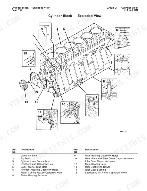
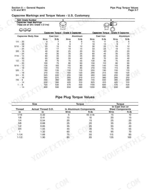
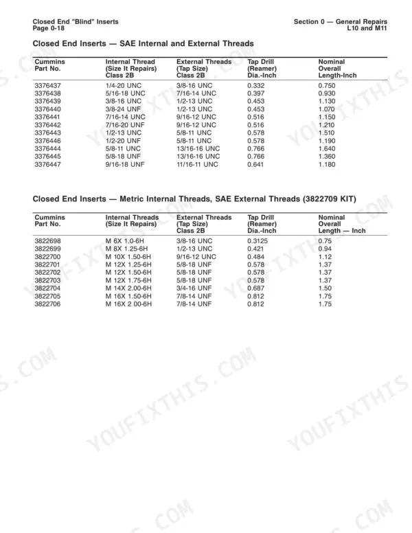
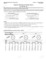
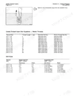
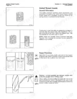
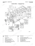
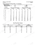
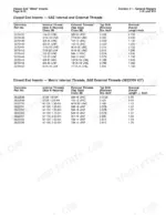
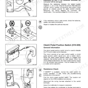
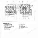
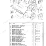
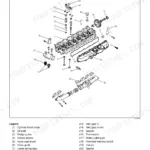
Crankshaft reconditioning is the toughest work in this 355-page Cummins L10 repair manual PDF (OEM ID 3810310-01): magnetic particle inspection, rod and main bearing journal grinding, balancing and polishing for the L10 and M11 engines. Beyond the crank, your block work runs through coiled and blind thread inserts, camshaft bore machining with bushings and salvage sleeves, main bearing bore repair, and liner counterbore cutting with manual or electric tools. Cylinder head chapters cover resurfacing, oversize valve guides, seat grinding and injector sleeve replacement. Exploded views and torque tables support the procedures. Hold liner protrusion at 0.00 mm to 0.13 mm [0.000 inch to 0.005 inch], and leave at least 99.24 mm [3.907 inch] of head thickness after resurfacing. Before ordering liner shims or oversize valve seat inserts, you can confirm which repair the block or head calls for. Bought once, the bookmarked, text-searchable file stays yours for this engine, liner clearances and resurfacing limits included.
What's Inside This Repair Manual
| System | Pages | Key Topics |
|---|
| Introduction | 5-18 | General Safety Instructions, General Repair Instructions, General Cleaning Instructions |
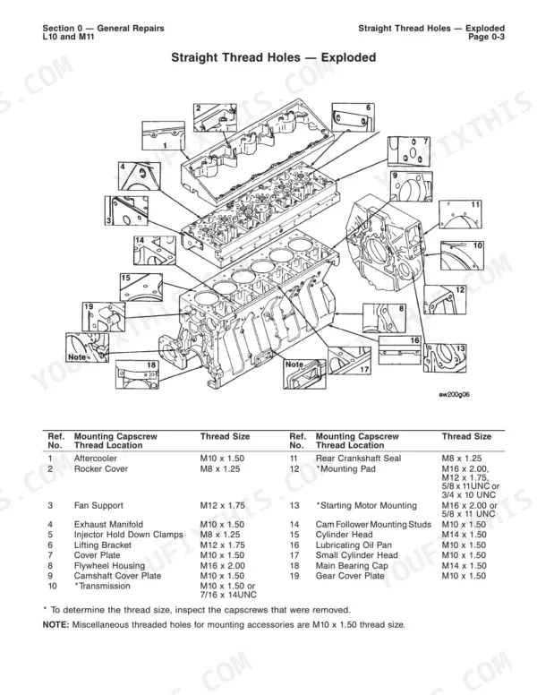
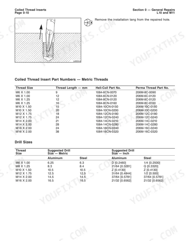
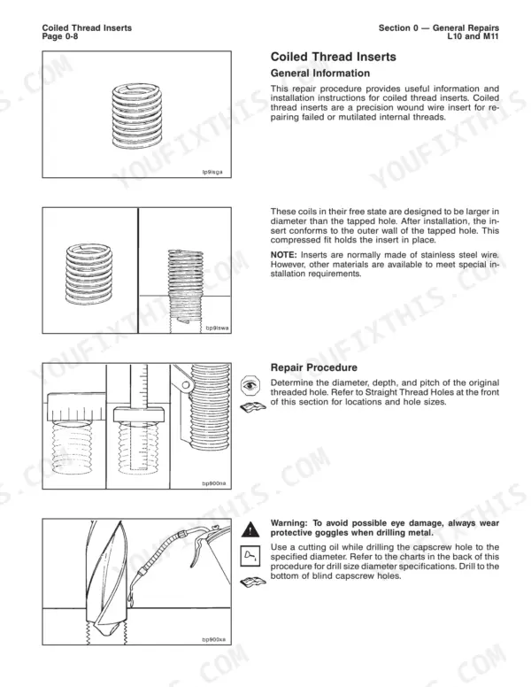
| General Repairs | 19-68 | Coiled Thread Inserts, Closed End Blind Inserts, Keylock Open End Thread Inserts |
| Camshaft Bore Repair | 69-95 | Camshaft Bore Cutting Tool, Camshaft Bushing, Salvage Sleeve, Camshaft Bore Machining |
| Piston Cooling Nozzle and Viscosity Sensor | 96-99 | Piston Cooling Nozzle Thread Repair, Viscosity Sensor Installation |
| Main Bearing Capscrew and Bore Repair | 100-140 | Main Bearing Capscrew Thread Repair, Main Bearing Bore Repair, Cylinder Block Idler Shaft Ring Dowel Bore Repair |
| Cylinder Liner Counterbore Machining | 141-163 | Manual Cutting Tool, Electric Cutting Tool, Liner Shims, Cylinder Liner Protrusion |
| Crankshaft Inspection and Reconditioning | 164-294 | Magnetic Particle Inspection, Grinding Connecting Rod Bearing Journals, Grinding Main Bearing Journals, Crankshaft Balancing, Polishing |
| Cylinder Head | 295-343 | Cylinder Head Resurfacing, Oversize Valve Guides, Oversize Valve Seat Inserts, Valve Seats Grinding, Injector Sleeve Replacement |
| Additional Service Literature | 344-349 | Service Products Catalog, Control Parts List, Parts Reuse Guidelines, Standard Repair Times, Shop Manuals, Troubleshooting and Repair Manuals |
| Component Manufacturers | 350-353 | Air Compressors, Alternators, Clutches, Governors, Hydraulic and Power Steering Pumps, Torque Converters |
Quick Reference Specifications
| Specification | Value | Page |
|---|
| Lubricating Oil Pump Mounting Capscrew Hole Drill Bit Size | 8.4 mm [21/64 inch] | p. 132 |
| Cylinder Liner Protrusion | 0.00 mm to 0.13 mm [0.000 inch to 0.005 inch] | p. 150 |
| Cylinder Liner to Cylinder Block Clearance | 0.25 mm [0.010 inch] minimum | p. 151 |
| Cylinder head resurfacing - maximum material removed per cut | 0.13 mm [0.005 inch] | p. 302 |
| Cylinder head resurfacing - minimum thickness after machining | 99.24 mm [3.907 inch] | p. 302 |
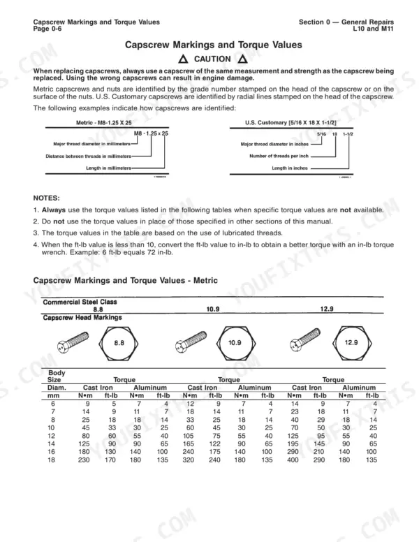
| Fixed Time Injector Hold Down with M10 x 1.50 Capscrews Torque | Step 1: 6 N·m [55 in-lb], Step 2: 12 N·m [110 in-lb], Step 3: 19 N·m [165 in-lb] | p. 304 |
| Fixed Time Injector Hold Down with M8 x 1.25 Capscrews Torque | Step 1: 5 N·m [45 in-lb], Step 2: 10 N·m [90 in-lb], Step 3: 15 N·m [130 in-lb] | p. 304 |
| Crankshaft Balance (per end) | 72 g·cm | p. 293 |
| Crankshaft Rotation Speed (Balancing) | 325 RPM | p. 287 |
| Crankshaft Rotation Speed (Grinding) | 50 RPM | p. 248 |
| Crankshaft Coolant Temperature | 13 to 24°C | p. 247 |