
Low oil pressure, a knock on combustion or an engine creeping toward overheat can each come from several causes. This book helps you find the right one before you start pulling parts. It is Cummins Service Manual Bulletin 4021592 for the QSK19, QSK19 CM850 MCRS and QSK19 CM2150 MCRS, with Volume 1 and Volume 2 in one file.
It covers industrial, marine, power generation and rail engines from teardown to run-in. That includes the cylinder block, cylinder head, overhead set, fuel, lube and cooling systems, the turbocharger and engine testing. The symptom trees list causes and corrections.
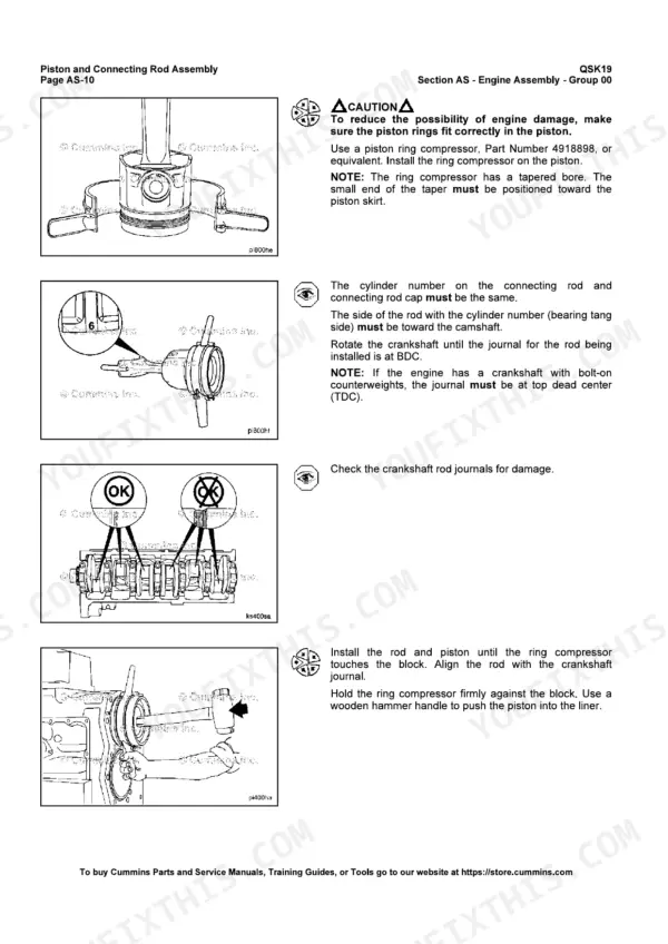
The main bearing, connecting rod and cylinder head torque sequences are in it for when the engine goes back together.
What's Inside This Cummins QSK19, QSK19 CM850 MCRS, QSK19 CM2150 MCRS Manual
| System | Pages | Key Topics |
|---|---|---|
| Volume 1 Introduction and Safety | 1-35 | Foreword, Contents, How to Use the Manual, Symbols, General Safety Instructions, Repair and Cleaning Guidelines, Acronyms |
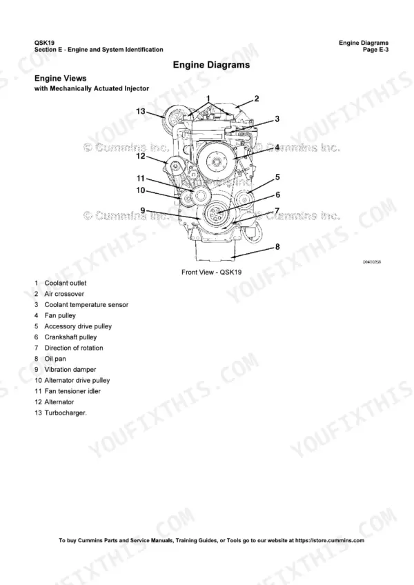
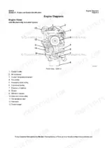
| Engine and System Identification | 36-61 | Engine Dataplates, Engine Diagrams of QSK19 Industrial and CM850 Heat Exchanger and Keel Cooled Engines, Service Model Nomenclature |
| Familiarization and Flow Diagrams | 62-129 | Fuel, Lubricating Oil, Cooling, Air Intake, Exhaust and Compressed Air Flow Diagrams, Injectors, Engine Mounting |
| Troubleshooting Symptoms | 130-207 | Troubleshooting Procedures and Symptom Trees: Air Compressor, Alternator, Coolant Temperature, Noise, Starting, Smoke, Fuel and Oil Consumption, Oil Pressure |
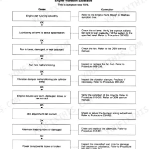
| Troubleshooting Symptoms (New Format) | 208-251 | ECM No Communication Troubleshooting Tree, Excessive Vibration Troubleshooting |
| Engine Disassembly | 252-331 | Water Pumps, Turbocharger, Wiring Harnesses, Injectors, Cylinder Heads, Fuel Pump, Pistons and Connecting Rods, Crankshaft and Bearings |
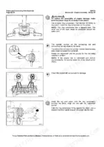
| Engine Assembly | 332-485 | Cylinder Liners, Crankshaft and Main Bearings, Pistons, Gear Train, Flywheel Housing, Cylinder Heads, Injectors, Overhead Set, Turbocharger, Harnesses |
| Engine Removal and Cylinder Block | 486-673 | Engine Removal, Installation and Long Term Storage; Connecting Rod, Main and Thrust Bearings, Camshaft, Crankshaft, Cylinder Liners, Pistons, Tone Wheel |
| Cylinder Head | 674-727 | Crossheads, Cylinder Head Inspection and Tightening, Head Gasket, Injector Protrusion |
| Rocker Levers and Cam Followers | 728-817 | Crankcase Breather, Overhead Set (OBC), Rocker Levers, Rocker Housings, Cam Followers, Push Rods |
| Fuel System and Volume 1 Index | 818-864 | Fuel Consumption, Fuel Pump, Fuel Shutoff Valve, Fuel Lift Pump, Volume 1 Index |
| Volume 2 Front Matter | 865-899 | Volume 2 Cover, Foreword, Contents and the Introduction and Safety Section Repeated From Volume 1 |
| Injectors and Fuel Lines | 900-1037 | Air in Fuel, Fuel Filters, Fuel Inlet Restriction, Fuel Supply Lines, Static Injection Timing, Injectors, Fuel Control Valve, High Pressure Supply Lines |
| Lubricating Oil System | 1038-1129 | Oil Cooler, Dipstick, Oil Filters, Oil Pan, Pressure Regulator, Oil Pump, Oil Pressure Diagnostics, Eliminator Filter |
| Cooling System | 1130-1277 | Drive Belts and Fan, Thermostats, Coolant, Radiator and Pressure Cap, Heat Exchanger, Sea Water Pump, Water Pump |
| Drive Units | 1278-1337 | Accessory Drive, Fuel Pump Drive, Hydraulic Pump Drive, Rear Gear Drive, Water Pump Drive |
| Air Intake System | 1338-1429 | Aftercooler, Air Crossover, Intake Manifold, Charge-Air Cooler, Air Intake Restriction, Turbocharger and Its Oil and Coolant Lines |
| Exhaust and Compressed Air Systems | 1430-1523 | Exhaust Manifold Dry and Wet, Exhaust Restriction, Holset Air Compressor, Air Governor |
| Electrical Equipment | 1524-1545 | Alternator, Drive Belt, Battery Cables, Starter Switch, Solenoid and Starting Motor |
| Engine Testing | 1546-1615 | Dynamometer Worksheet, Chassis and Engine Dynamometer Run-In, Run-In Without Dynamometer, Engine Compression Test |
| Mounting Adaptations | 1616-1645 | Front Support Bracket, Flywheel, Flywheel Housing, Ring Gear, Engine Mounts, Rock Shields |
| Service Literature | 1646-1651 | Additional Service Literature List, Ordering Locations, Customized Parts Catalog |
| Specifications | 1652-1799 | Specifications and Torque Values by Group, General Engine, Fuel, Oil, Cooling, Air Intake, Exhaust and Electrical Data, Filter Specifications, Belt Tension, Capscrew Torques, Conversions |
| Volume 2 Index and Foldouts | 1800-1808 | Volume 2 Index, QSK19 CM2150 Industrial Wiring Diagram Foldout, Fault Code Information Foldout |
Quick Reference Specifications
| Specification | Value | Page |
|---|---|---|
| Displacement | 19 liters [1150 cu in] | p. 1779 |
| Bore and stroke | 158.75 mm x 158.75 mm [6.25 in x 6.25 in] | p. 1779 |
| Firing order | 1, 5, 3, 6, 2, 4 | p. 1779 |
| Intake valve adjustment | 0.36 mm [0.014 in] | p. 1779 |
| Exhaust valve adjustment, electronic injectors | 0.69 mm [0.027 in] | p. 1779 |
| Exhaust valve adjustment, mechanical injectors | 0.81 mm [0.032 in] | p. 1779 |
| Injector OBC method adjustment, mechanical injectors | 19 N•m [165 in-lb] | p. 1779 |
| Compression ratio, engines with electronic injectors | 16.0:1 | p. 1779 |
| Oil pressure at idle, minimum (15W-40 at 107° C) | 138 kPa [20 psi] | p. 1781 |
| Oil pressure at no-load governed speed (15W-40 at 107° C) | 345 to 483 kPa [50 to 70 psi] | p. 1781 |
| Coolant capacity, engine only, electronic injectors | 42.2 liters [44 qt] | p. 1782 |
| Coolant capacity, engine only, hydromechanical injectors | 32.2 liters [34 qt] | p. 1782 |
| Standard modulating thermostat range | 82° to 94°C [180° to 202°F] | p. 1782 |
| Maximum pressure cap relief (at sea level) | 103 kPa [15 psi] | p. 1782 |
| Fuel pump pressure minimum at 1800 rpm, mechanical injectors | 1655 kPa [240 psi] | p. 1780 |
| Fuel inlet restriction maximum, dirty filter, electronic injectors | 34 kPa [10 in-Hg] | p. 1780 |
| Air intake restriction maximum, dirty filter | 635 mm-H₂O [25 in-H₂O] | p. 1783 |
| Main bearing capscrews | 265 N•m [195 ft-lb] → 605 N•m [445 ft-lb] → loosen all → 265 N•m [195 ft-lb] → 605 N•m [445 ft-lb] | p. 526 |
| Cylinder head capscrews | 68 N•m [50 ft-lb] → 203 N•m [150 ft-lb] → 298 N•m [220 ft-lb] → advance 90 degrees | p. 720 |
| Connecting rod capscrews | 102 N•m [75 ft-lb] → 197 N•m [145 ft-lb] → 292 N•m [215 ft-lb] → 366 N•m [270 ft-lb] → loosen both → 102 N•m [75 ft-lb] → 149 N•m [110 ft-lb] | p. 1698 |
Cummins QSK19, QSK19 CM850 MCRS, QSK19 CM2150 MCRS Common Problems This Manual Covers
Lubricating oil pressure low
Start with the dipstick. If the oil level is below specification, fill it to the correct level. Then look for external oil leaks and tighten or replace the gaskets that are weeping. If the oil filter is plugged, change the oil and the filters. The symptom tree in Troubleshooting Symptoms takes you through each check in order.
Manual Section: Troubleshooting Symptoms p. 199Engine will not crank or cranks slowly with an air starter
Check the air tanks first. If the pressure is low, raise it from an external source. If the oil is too cold, install an oil pan heater or fill the engine with warm oil. Inspect the starting motor pinion and ring gear and replace any damaged parts. If the engine still will not turn, suspect hydraulic lock. Remove the injectors and bar the engine over. The full tree is in Troubleshooting Symptoms.
Manual Section: Troubleshooting Symptoms p. 178Engine noise excessive, combustion knocks
Read the electronic fault codes first. If any are active, troubleshoot those codes before you touch anything else. Next, find and remove any air in the fuel system. Replace any injector that is malfunctioning. Finally, measure the overhead set and adjust it to specification using the rocker levers section. The order of these checks comes from the Troubleshooting Symptoms tree.
Manual Section: Troubleshooting Symptoms p. 172Coolant temperature above normal, gradual overheat
First test the coolant temperature gauge itself and replace it if it is faulty. If the coolant level is below specification, find the leak and check the oil for coolant. Clean any damaged or debris-packed radiator fins. Tighten a loose fan drive belt. The Troubleshooting Symptoms tree and the Cooling System section cover each step.
Manual Section: Troubleshooting Symptoms p. 157Frequently Asked Questions
Does this manual cover my Cummins QSK19, QSK19 CM850 MCRS or QSK19 CM2150 MCRS engine?
Yes. It is Cummins Service Manual Bulletin 4021592 for those three engines, with Volume 1 and Volume 2 in one file. It covers industrial, marine, power generation and rail engines. MCRS stands for Modular Common Rail System. The book does not list engine serial number ranges, so check your engine dataplate before you order. p. 1
What are the Cummins QSK19 valve adjustment settings and firing order?
Intake valve lash is 0.36 mm [0.014 in]. Exhaust lash is 0.69 mm [0.027 in] with electronic injectors and 0.81 mm [0.032 in] with mechanical injectors. On mechanical injectors, the injector OBC method adjustment is 19 N•m [165 in-lb]. Firing order is 1, 5, 3, 6, 2, 4. The full overhead set procedure is in the rocker levers section. p. 1779
What is the normal QSK19 oil pressure and how much coolant does the engine hold?
With 15W-40 oil at 107° C, minimum oil pressure at idle is 138 kPa [20 psi]. At no-load governed speed it is 345 to 483 kPa [50 to 70 psi]. Engine-only coolant capacity is 42.2 liters [44 qt] with electronic injectors and 32.2 liters [34 qt] with hydromechanical injectors. The standard modulating thermostat range is 82° to 94°C [180° to 202°F]. p. 1781
What are the QSK19 cylinder head, main bearing and connecting rod torque values?
Cylinder head capscrews go to 68 N•m [50 ft-lb], then 203 N•m [150 ft-lb], then 298 N•m [220 ft-lb], then advance 90 degrees. Main bearing capscrews go to 265 N•m [195 ft-lb] and then 605 N•m [445 ft-lb]. Loosen them all and repeat both steps. Connecting rod capscrews take seven steps. They run up to 366 N•m [270 ft-lb], are loosened, and then finish at 102 N•m [75 ft-lb] and 149 N•m [110 ft-lb]. p. 720
What is inside this manual: rebuild procedures, troubleshooting, wiring diagrams?
It has complete rebuild procedures and specifications, from engine disassembly and assembly through every group from the cylinder block to mounting adaptations. It also covers engine testing, run-in, torque values and troubleshooting symptom trees. It includes the wiring diagram for the QSK19 CM2150 Industrial Modular Common Rail System. There are also flow diagrams for the fuel, oil and cooling systems. Electronic troubleshooting for the fuel system is in a separate Cummins bulletin, not this one. p. 3

Reviews
There are no reviews yet.