
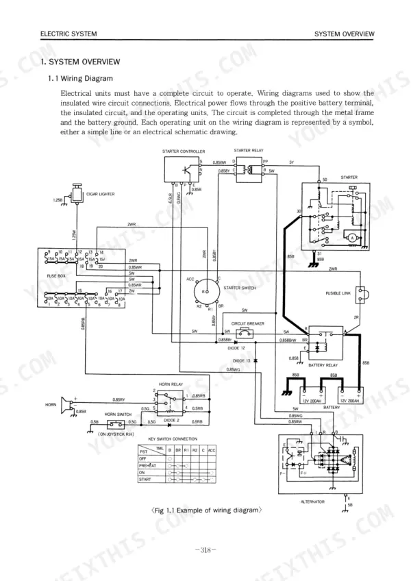
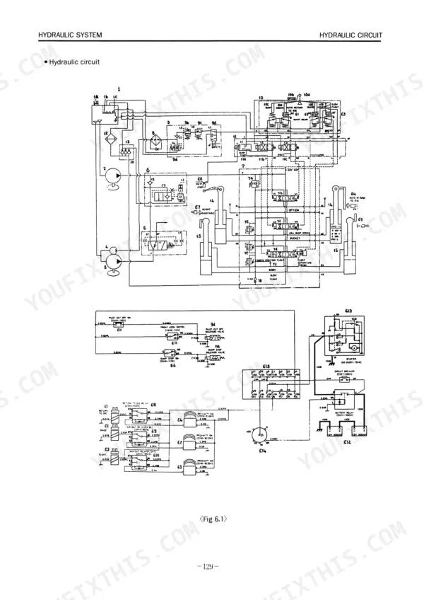
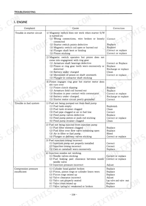
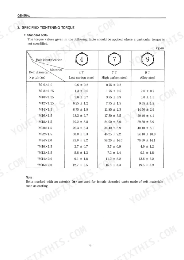
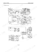
Engine and wheel loader, end to end: this 365-page Daewoo DB58T and MEGA200 service manual PDF runs from the DB58T diesel's cylinder head, fuel injection and turbocharger through the MEGA200's powershift transmission, planetary axles, brakes, steering and electrical system. Hydraulic schematics trace oil from the main pump through the main control valve and remote control valve out to the hydraulic cylinders and accumulator, and wiring diagrams map the starting, preheating, charging and monitoring circuits. The torque converter and transmission section fills more than a quarter of the book, taking you through clutch arrangement and modulation before the axle and wet disc brake chapters. Set intake and exhaust valves to 0.40 mm cold, and pull connecting rod cap bolts to 12 ± 0.25 kg-m. Chasing a clutch modulation fault through a powershift without factory data eats whole days. Bookmarks split the engine from the loader, the text searches cleanly, and your MEGA200 is back cycling material sooner.
What's Inside This Manual
| System | Pages | Key Topics |
|---|---|---|
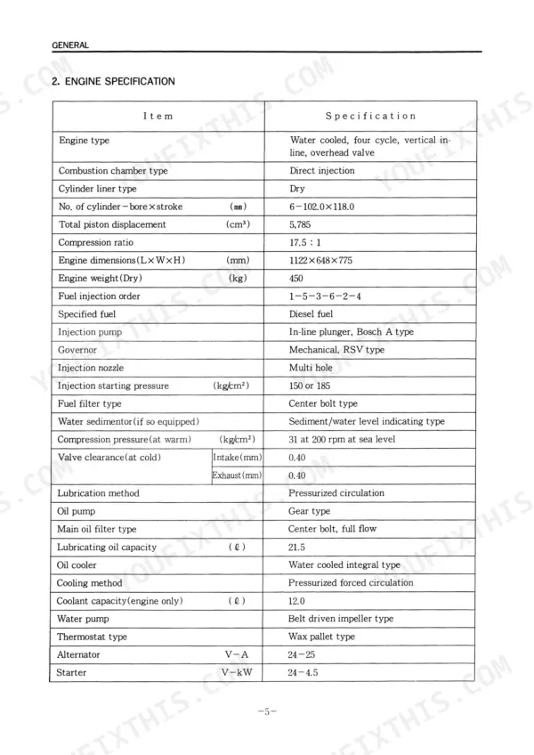
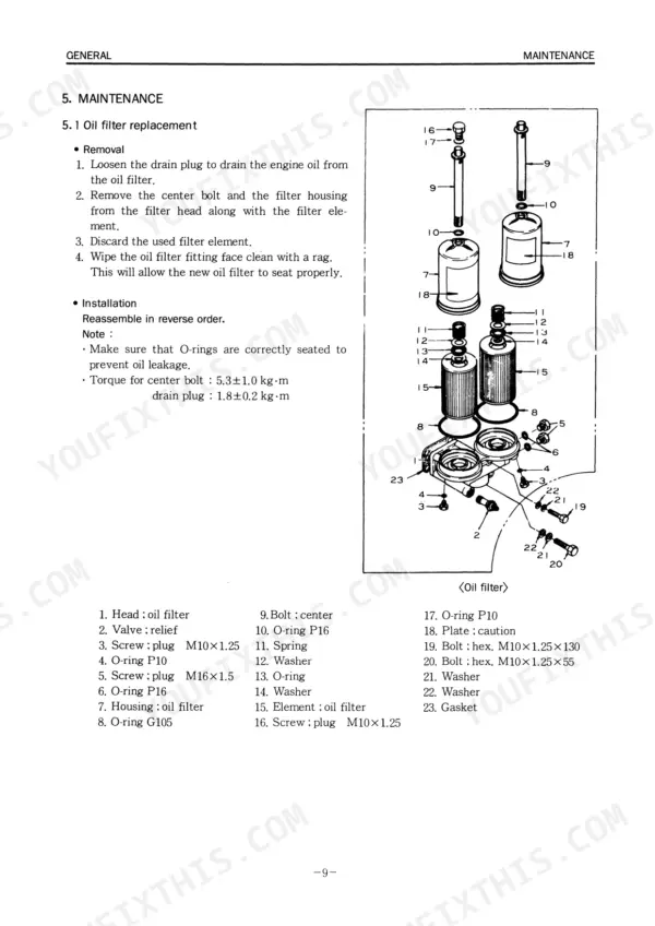
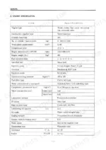
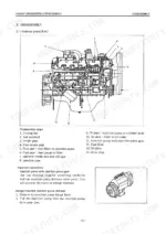
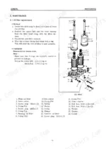
| Engine DB58T | 5-26 | Engine Specification, Specified Tightening Torque, Oil Filter Replacement, Fuel Filter Replacement, Injection Timing, Compression Pressure Measurement, Turbocharger Inspection |
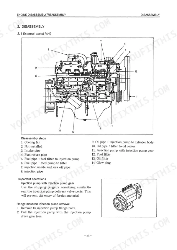
| Engine Disassembly and Reassembly | 27-82 | External Parts, Major Components, Rocker Arm Shaft, Cylinder Head, Piston, Connecting Rod |
| Lubricating System | 83-90 | Lubricating Oil Circuit, Oil Pump, Oil Filter, Oil Cooler |
| Cooling System | 91-98 | Coolant Circuit, Water Pump, Thermostat |
| Fuel System | 99-106 | Fuel Circuit, Fuel Filter, Injection Nozzle |
| Turbocharger | 107-110 | General Description, Turbocharger Identification, Rotor Shaft Play Inspection |
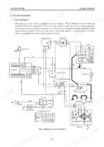
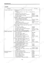
| Troubleshooting | 111-116 | Hydraulic Circuit Diagram, Electric Circuit Diagram, Worldwide Net Work |
| Wheel Loader Mega200 | 117-130 | Machine Specification, Assembly Drawing, Main Parts and Functions, Control Station, Gauges and Switches, Control Levers |
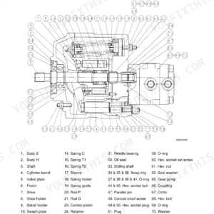
| Hydraulic System | 131-164 | Hydraulic Circuit, Main Control Valve, Main Pump, Remote Control Valve, Hydraulic Cylinder, Accumulator |
| Torque Converter and Transmission | 165-268 | Torque Converter, Powershift Transmission, Clutch and Gear Arrangement, Transmission Clutch Modulation |
| Axles | 269-292 | Self-Locking Differential, Final Reduction Planetary Gear, Wet Disc Brake, Parking Brake |
| Brake System | 293-300 | Hydraulic Circuit, Service Brake, Parking Brake, Brake Pedal Valve, Brake Supply Valve, Accumulator |
| Steering System | 301-320 | Hydraulic Circuit, Steering Valve, Cushion Valve, Priority Valve, Unloader Valve |
| Electrical System | 321-364 | Battery, Engine Starting System, Engine Stop System, Engine Preheating System, Charging System, Monitoring System |
| Worldwide Network | 365 |
Quick Reference Specifications
| Specification | Value | Page |
|---|---|---|
| Intake and exhaust Valve clearance(cold) | 0.40 mm | p. 19 |
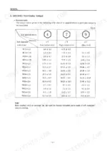
| Torque for new bolts of cylinder head | 7.0-9.5 kg-m | p. 11 |
| Torque for new bolts of cylinder head | 7.0 -> 9.5 ± 0.5 kg-m | p. 11 |
| Torque for reused bolts of cylinder head | 7.0-11.5 kg-m | p. 11 |
| Torque for bolts holding crankshaft bearing cap | 2.4 ± 1 kg-m | p. 11 |
| Torque for bolts of connecting rod bearing cap | 12 ± 0.25 kg-m | p. 11 |
| Torque for bolts holding flywheel to crankshaft | 22.3 ± 2.2 kg-m | p. 11 |
| Torque for bolts holding flywheel to crankshaft | 22.3 ± 2.2 kg-m | p. 11 |
| Torque for center bolt | 5.3 ± 1.0 kg-m | p. 13 |
| Torque for drain plug | 1.8 ± 0.2 kg-m | p. 13 |
| Main bearing cap torque | 24.1 ± 1 kg·m (173.5 ± 7.2 lb.ft) | p. 57 |
| Connecting rod and bearing cap bolt tightening torque | 12 ± 0.25 kg·m | p. 51 |


