Getting a Daewoo Mega 400-III Plus wheel loader back to full lift, steering and drive is the outcome this 532-page shop manual PDF (OEM 4023-7130E) is built around. Hydraulics take up roughly a third of the book, working through the Vickers 35VQ main pump, steering and brake pump, Danfoss flow amplifier, Rexroth brake pedal valve, accumulator and cylinders before ending on a full hydraulic schematic. The ZF transmission, torque converter and Graziano axles claim even more, and an electrical schematic with fault code tables lets you trace a dead circuit to the wire. Set K3 clutch plate clearance at 2.2 to 2.4 mm, and confirm the engine speed input reads between its 0.45 V and 7.00 V thresholds before you condemn the sensor. Guess a clearance and you pay for a second teardown. Bookmarked sections and a searchable text layer take you straight to the figure, and your loader is cycling material again.
What's Inside This Manual
| System | Pages | Key Topics |
|---|
| Safety | 7-28 | Wheel Loader Safety |
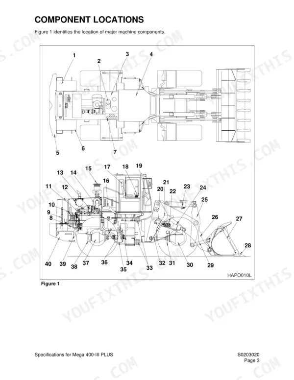
| Specifications | 29-44 | Specifications for Mega 400-III PLUS |
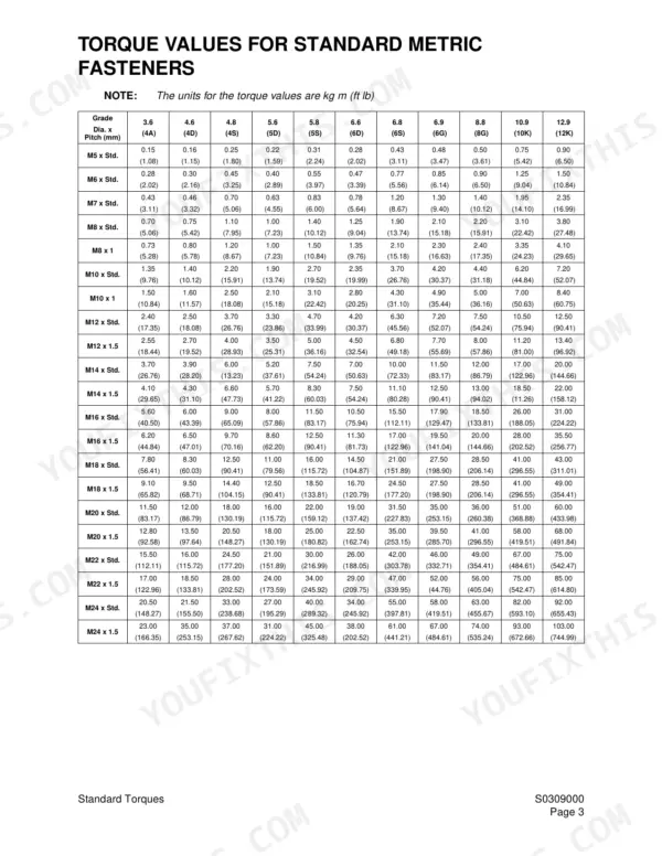
| General Maintenance | 45-72 | General Maintenance Procedures, Standard Torques |
| Upper Structure | 73-74 | |
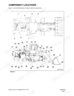
| Lower Structure and Chassis | 75-76 | |
| Front Axle | 79-118 | General Description, Parking Brake, Limited Slip Differential, Front Planetary Gear Set, Scheduled Maintenance |
| Rear Axle | 119-150 | General Description, Rear Axle Differential, Rear Axle Planetary Gear Set, Scheduled Maintenance, Lubricant Specifications, General Disassembly and Reassembly Instructions |
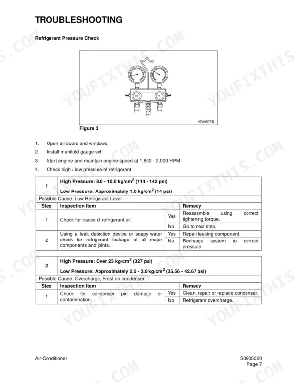
| Air-Conditioner | 151-168 | Refrigerant Circulation, Air-Conditioning System Circuit Diagram, Troubleshooting, Refrigerant Recovery, Leakage Check, Refrigerant Charging |
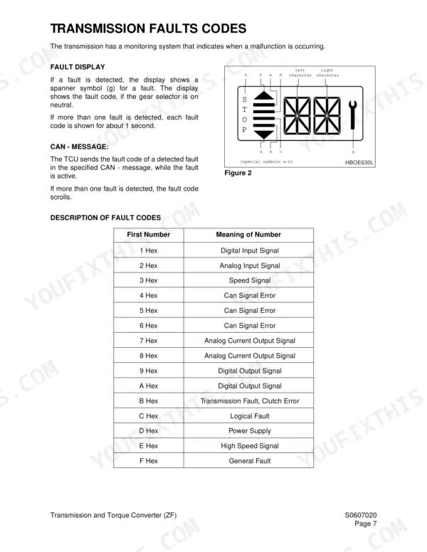
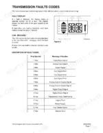
| Transmission and Torque Converter | 169-306 | Drive Train Description, Transmission, Transmission Faults Codes, Definition of Operation Modes, Table of Fault Codes, Measurement of Resistance at Actuator/Sensors and Cable |
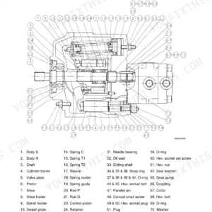
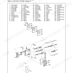
| Hydraulics | 307-492 | Hydraulic System, Accumulator, Cylinders, Main Pump, Steering and Brake Pump, Brake Pedal Valve, Flow Amplifier, Power Steering Unit |
| Electrical System | 493-530 | Electrical System Procedures |
| Attachments | 531-532 | |
Quick Reference Specifications
| Specification | Value | Page |
|---|
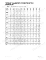
| Standard Metric Fasteners Torque | 0.15 kg m to 103.00 kg m | p. 63 |
| Standard U.S. Fasteners Torque (Grade 5) | 6 ft. lbs. to 3550 ft. lbs. | p. 65 |
| Engine speed input voltage threshold (high) | 7.00 V | p. 179 |
| Engine speed input voltage threshold (low) | 0.45 V | p. 179 |
| Plate clearance - K3 | 2.2 - 2.4 mm | p. 248 |
| Inner plate thickness (optional) | 2.0 - 4.0 mm | p. 247 |
| Bearing cover hex. head screw torque limit (M10/8.8) | 4.69 kg•m (33.93 ft lbs) | p. 285 |
| Bolt hex. head screw torque limit (M10/8.8) | 4.69 kg•m (33.93 ft lbs) | p. 285 |
| Pump flange/pump hex. head screw torque limit (M12/8.8) | 8.06 kg•m (58.27 ft lbs) | p. 288 |
| Pump flange (power take off) hex. head screw torque limit (M14/8.8) | 12.75 kg•m (92.20 ft lbs) | p. 288 |
| Continuous backup ring water temperature | 30 - 50°C (86 - 122°F) | p. 348 |
| Continuous backup ring soak time | 2 - 3 minutes | p. 348 |