| Safety | 1-23 | To the Operator of a Daewoo Excavator, General Safety Essentials, Location of Safety Labels, Work-Site Precautions, Operation, Maintenance |
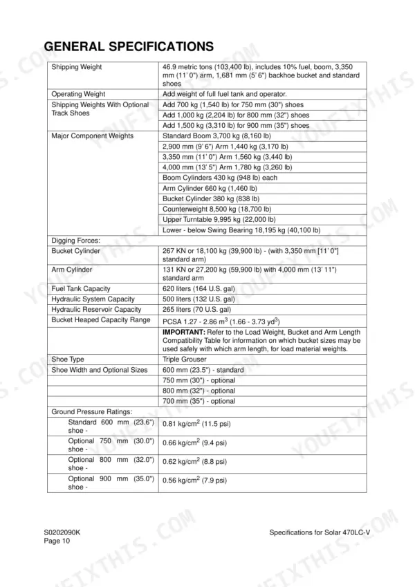
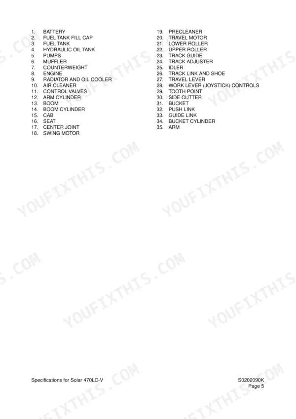
| Specifications | 24-46 | General Description, Component Locations, General Dimensions, Working Range, General Specifications, Engine Performance Curves, Performance Tests |
| General Maintenance | 47-73 | General Maintenance Procedures, Standard Torques |
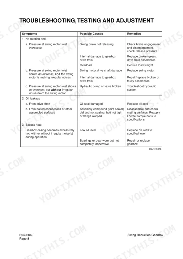
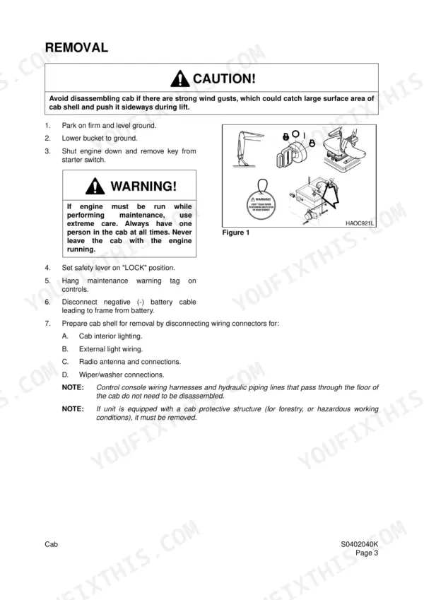
| Upper Structure | 74-134 | Cab, Counterweight, Fuel Tank, Fuel Transfer Pump, Swing Bearing, Swing Reduction Gearbox |
| Lower Structure and Chassis | 135-165 | Track Tension, Wear Limits and Tolerances, Track Shoes and Links, Front Idler Roller, Track Removal and Installation |
| Engine and Drive Train | 166-198 | Air-Conditioner, Drive Coupling (Main Pump) |
| Hydraulic System Troubleshooting, Testing and Adjustment | 199-229 | Hydraulic Schematic, Operation of Working Components, Pilot Pressure, Swing System Troubleshooting, Control Valve Troubleshooting |
| Accumulator | 230-233 | General Description, Specifications, Nitrogen Charge, Diaphragm |
| Center Joint (Swivel) | 234-241 | General Description, Parts List, Testing, Disassembly, Reassembly |
| Cylinders | 242-261 | Theory of Operation, Parts List, Piston Nut, Disassembly, Reassembly |
| Swing Motor | 262-289 | Theory of Operation, Swing Motor Anti-Cavitation Make-Up Valve, Relief Valve, Swing Brake Operation, Disassembly, Reassembly |
| Travel Motor (with Gearbox) | 290-349 | Reduction Gearbox Operation, Travel Motor Disassembly, Travel Motor Reassembly, Rotary Group Adjustment, Assembly of Port Plate |
| Main Pump (Rexroth) | 350-401 | General Repair Guidelines, Control Module, Removing the Controller, Rotary Group, Pump Assembly, Tightening Torques |
| Main Control Valve (Kayaba) | 402-451 | Theory of Operation, Anti-Drift Valve, Main Relief Valve, Disassembly, Reassembly |
| Pilot Control Valve (Work Lever / Joystick) | 452-471 | Theory of Operation, Structure and Function, Disassembly, Reassembly, Adjustment |
| Travel Control Valve (with Damper) | 472-495 | Pressure Reducing Valve, Damper Mechanism, Disassembly, Reassembly, Start-Up Procedures |
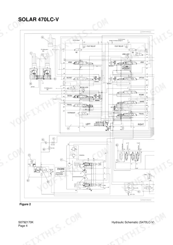
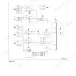
| Hydraulic Schematic (Solar 470LC-V) | 496-501 | Pump, Main Control Valve, Swing and Travel Circuits on Facing-Page Sheets |
| Electrical System | 502-576 | Electric Supply System, Starting and Charging Circuits, e-EPOS Controller, Instrument Panel, Failure Information Codes |
| Electrical Schematic (Solar 470LC-V) | 577-582 | Lamp, Starting, Charging and Monitor Circuits with Wire Gauges and Colours, On Facing-Page Sheets |
| Attachments | 583-601 | Front Attachment Pin Specifications, Arm and Boom Removal and Installation, Bucket Tooth Replacement, Bucket O-Ring and Shimming, Bucket Reversal |