
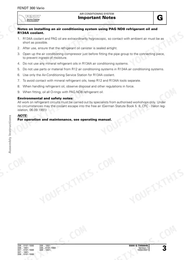
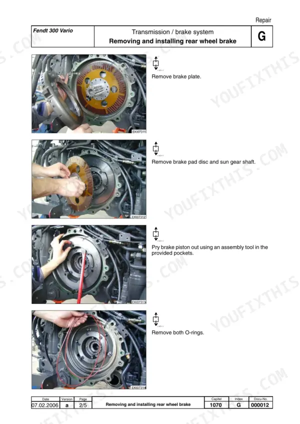
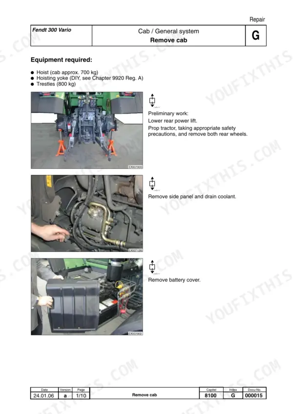
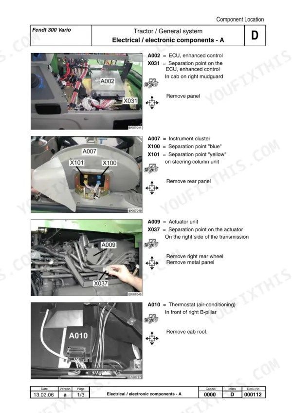
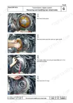
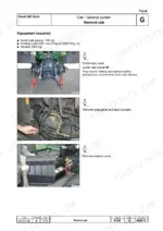
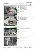
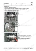
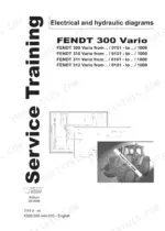
More than 1,100 pages of Fendt factory data, all aimed at one thing: fixing your 300 Vario yourself instead of waiting in the dealer's queue. This is AGCO manual X990.005.056.010, Edition 10/2007, for the COM III 309, 310, 311 and 312 Vario.
It starts at the Deutz TCD 2012 L4 4V with common rail and EDC 7. From there it covers the Vario transmission, PTOs, front wheel drive, EPC power lift, cab and air conditioning. You also get circuit diagrams, hydraulic schematics, calibration codes and the full fault code table. If you guess a torque on an axle drive or a hydraulic pressure, you find out you were wrong when a thread strips or a hose lets go.
Keep it on a tablet in the cab or a laptop on the bench. The figures go wherever the tractor stops, and you get back in the field before the weather turns.
What's Inside This Fendt 309 Vario, 310 Vario, 311 Vario, 312 Vario Manual
| System | Pages | Key Topics |
|---|---|---|
| General Information and Technical Data (Group 0000) | 1-19 | Cover, Assembly Overview, Documentation Structure, Tightening Torques for Bolts, History and Selected Technical Data per Model, Towing Instructions |
| Vario Tractors Fault Codes | 20-40 | Fault Code Table: Fault Code, ID Code, Description, Consequences, Circuit Diagram Link, Fendias Note |
| Component Location | 41-104 | Electrical and Electronic Components a to Y, Hydraulic Components |
| Setting and Calibration | 105-153 | General Points on Calibration, Calibration Codes 8001/8002, 7666, 6034, 7034, 4001, 4002, 4005, 4007, 4009 |
| Transmission Control Unit (Group 1005) | 154-182 | General, Transmission Control Unit Functional Sequence, Documents and Diagrams, Testing |
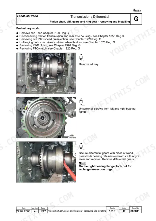
| Differential, Axle Drives, Hand Brake and Housing (Groups 1010-1050) | 183-225 | Differential Repair, Axle Drives, Hand Brake Setting and Repair, Transmission Housing |
| Brake System and Transmission Unit (Groups 1070-1080) | 226-244 | Brake Adjuster, Brake System Repair, Transmission Unit Repair |
| Front PTO and Live PTO (Groups 1200-1220) | 245-277 | Front PTO Assembly Instruction, Live PTO Repair |
| Front Wheel Drive (Group 1320) | 278-287 | Front Wheel Drive Repair |
| Engine: General System, Cylinder Head and Fuel System (Groups 2000-2060) | 288-346 | Deutz Common Rail System Description, EMR 2 vs EMR 3, Cylinder Head Setting, Fuel System |
| Engine: Heater, Lubrication, Exhaust and Injectors (Groups 2250-2712) | 347-370 | Engine Heater, Lubrication Component Location and Testing, Exhaust System, Injectors Repair |
| Air Conditioning System (Group 5500) | 371-386 | Compressor, Condenser and Fluid Reservoir, Coolant Lines, Evaporator, Temperature Control, Evacuating and Filling, Air Conditioning Circuit Diagram |
| Cab, Heater and Windscreen Wipers (Groups 8100-8117) | 387-412 | Cab Repair, Heater, Windscreen Wipers |
| Power Lift EPC and Air Compressor (Groups 8610-8800) | 413-425 | Electrohydraulic Control EPC Faults and Diagrams, Air Compressor Documents and Component Location |
| Electrical Circuit Diagrams (Group 9000) | 426-643 | Fuses X050, X051 and A013, Component Overviews, Circuit Diagram Sheets per Chassis-Number Range |
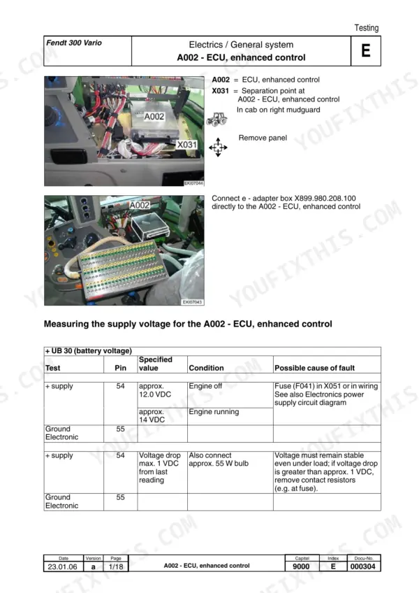
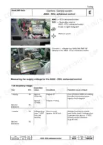
| Electrical Testing: Control Units (A002-A051) | 644-743 | ECU Enhanced Control, Instrument Cluster, Actuator Unit, Fuse Circuit Board A013, EPC B, Control Panel, Engine Control Unit A051 Pin Assignment |
| Electrical Testing: Sensors and CAN Bus | 744-909 | Speed, Position, Pressure and Temperature Sensors B002-B092, CAN Bus Enhanced Control and Transmission Bus |
| Electrical Testing: Lights, Battery, Motors and Switches | 910-1016 | Work Lights, Battery, Generator, Starter Motor, Wiper and Blower Motors, Switches S005-S084 |
| Electrical Testing: Solenoid Valves and Injectors | 1017-1119 | Clutch, Engine Brake, PTO, 4WD, Differential Lock, Suspension, Power Lift Solenoid Valves, Metering Unit, EGR Servomotor, Injectors |
| Starter Lockout, Front Power Lift and Hydraulic Pump (Groups 9015-9400) | 1120-1131 | Battery Disconnector, Front Power Lift Repair, Hydraulic Pump Assembly |
| Hydraulics and Valve Assemblies (Groups 9600-9620) | 1132-1162 | Technical Specifications, Hydraulic Circuit Diagrams and Keys, Valve Assemblies, Testing |
| Electronics Retrofit and Special Tools (Groups 9700-9920) | 1163-1185 | Retrofitting TMS and 4WD/Differential Lock Auto Mode, Special Tools |
Quick Reference Specifications
| Specification | Value | Page |
|---|---|---|
| Engine type | Deutz TCD 2012 L4 4V | p. 11 |
| Rated power ECE-R24 (kW/HP) | 59 / 80 (309 Vario) / 66 / 90 (310 Vario) / 74 / 100 (311 Vario) / 81 / 110 (312 Vario) | p. 11 |
| Max. power ECE-R24 (kW/HP) | 70 / 95 (309 Vario) / 77 / 105 (310 Vario) / 84 / 115 (311 Vario) / 92 / 125 (312 Vario) | p. 11 |
| Bore / stroke | 101 / 126 mm | p. 11 |
| Cubic capacity | 4.04 l | p. 11 |
| Rated speed | 2100 rpm | p. 11 |
| Idle speed | 780 +/- 30 rpm | p. 11 |
| No-load speed | 2200 - 2250 rpm | p. 11 |
| Valve clearance inlet / outlet (cold engine max. 50°C) | 0.4 / 0.5 mm | p. 11 |
| Compression ratio | 18 : 1 | p. 11 |
| Firing order | 1-3-4-2 | p. 11 |
| Compression pressure | 20 ... 30 bar (max. perm. deviation between cylinders is 15%) | p. 12 |
| Min. oil pressure in warm state (114 °C) and low idle | approx. 0.8 bar | p. 12 |
| Fuel tank | 210 l | p. 12 |
| Pump PK (working hydraulics) max. pressure | 200 bar | p. 1132 |
| Pump PK delivery at rated engine speed 2100 rpm | 48 l/min | p. 1132 |
| Pump PL (steering pump) delivery at rated engine speed 2100 rpm | 30 l/min | p. 1132 |
| Maximum available oil quantity | approx. 45 l | p. 1132 |
| Continuous lifting power at rear power lift | 46.4 KN (4.6 tons) | p. 1132 |
| Continuous lifting power at front power lift | 28.4 KN (2.8 tons) | p. 1132 |
Fendt 309 Vario, 310 Vario, 311 Vario, 312 Vario Common Problems This Manual Covers
No functions available and no display, with a bus error logged
Read the fault memory first. Codes 00.0.04, 00.0.05 and 00.0.06 sit against Id A002, the enhanced control ECU, as bus errors. The fault code table links them to the Electronics voltage supply circuit diagram. Check the 500 mA microfuses on the A013 printed circuit board and fuses X050/X051 before you chase the CAN bus.
Manual Section: Vario Tractors Fault Codes / Electrical Circuit Diagrams (Group 9000) p. 20Water-in-fuel notice showing in the multiple display
The B091 sensor measures water level in the water separator and flags the display when it reaches maximum. Drain the water and dirt from the separator first. If the notice stays on after draining, use the Sensors and CAN Bus testing section to check B091 itself before you blame the fuel.
Manual Section: Electrical Testing: Sensors and CAN Bus p. 876Engine will not crank because of the starter lockout
Before you pull the starter, check S074, the transmission neutral / starter lockout switch on the left of the steering column. It reports to A002, so a tired switch or a corroded plug can look like a dead starter. The switches testing section covers S074, and Group 9015 covers the battery disconnector.
Manual Section: Electrical Testing: Lights, Battery, Motors and Switches / Starter Lockout (Group 9015) p. 1000Vario drive feels wrong after a transmission repair
Run calibration code 4007 to relearn the transmission ratio characteristic after any transmission work. As the Setting and Calibration section specifies, apply the hand brake and put the transmission in idle first. Read the general points on calibration beforehand so the procedure is not interrupted halfway through.
Manual Section: Setting and Calibration (calibration code 4007) p. 132Frequently Asked Questions
Does this cover my 309 Vario, or only the bigger 312?
It covers all four COM III models: 309, 310, 311 and 312 Vario. They all run the Deutz TCD 2012 L4 4V with 4.04 l, Deutz common rail (DCR) and EDC 7 (Bosch). Rated power ECE-R24 is 59 / 80 kW/HP on the 309, 66 / 90 on the 310, 74 / 100 on the 311 and 81 / 110 on the 312. p. 11
The dash went dark and nothing works. Where do I start?
Pull the fault memory and look for 00.0.04, 00.0.05 or 00.0.06 against Id A002. Those are bus errors on the enhanced control ECU. The fault code table sends you to the Electronics voltage supply circuit diagram. Check the 500 mA microfuses on the A013 board before you start chasing wiring. p. 20
Do I have to recalibrate after transmission work?
Usually, yes. Calibration code 4007 relearns the transmission ratio characteristic, with the hand brake applied and the transmission in idle. The Setting and Calibration section also lists 8001/8002, 7666, 6034, 7034, 4001, 4002, 4005 and 4009. Read its general points before you start any of them. p. 132
What are the valve clearance and compression figures for the Deutz in these Fendt tractors?
Valve clearance is 0.4 / 0.5 mm inlet / outlet, set on a cold engine at max. 50°C. Compression pressure is 20 ... 30 bar, with a max. perm. deviation between cylinders of 15%. Firing order is 1-3-4-2 and compression ratio is 18 : 1. Idle should be 780 +/- 30 rpm. p. 11
The circuit diagrams are in German. Can I still use them?
The diagram sheets and hydraulic circuit diagrams carry German component labels. Every part also has an Id code like A002, B091 or S074. Look that code up in the English Component Location section, which runs A to Y, and in the hydraulic keys in Group 9600. That way you can trace a circuit without knowing any German. p. 41


Reviews
There are no reviews yet.