

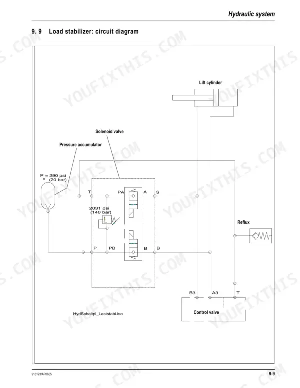
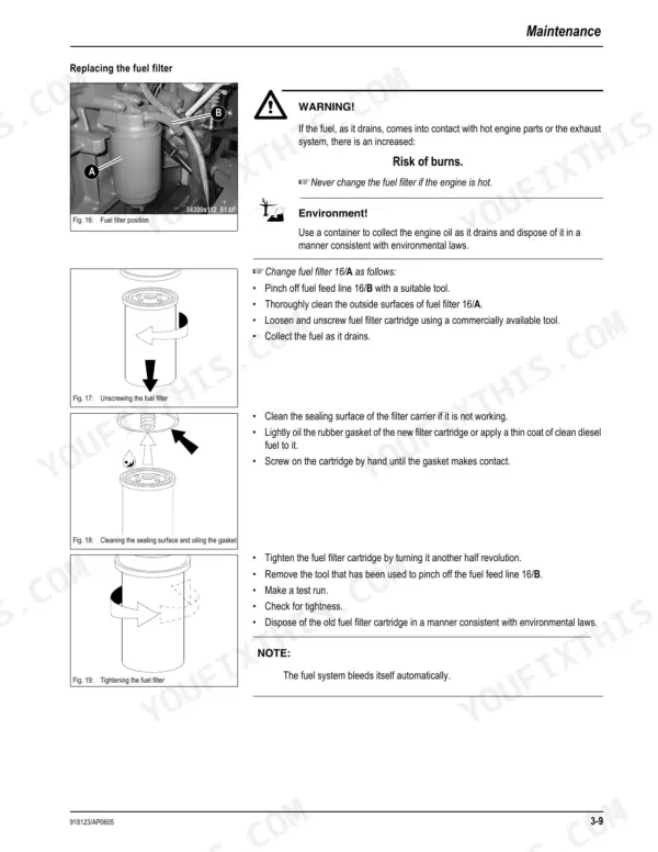


This is the factory service manual for the Gehl 680 wheel loader, Form No. 918123, for the 2005 build beginning at serial number 343010001. Across 212 pages it documents the Deutz BF4M 2011 diesel, rated at 75 hp (56 kW), and covers the machine from operation through the electrical system.
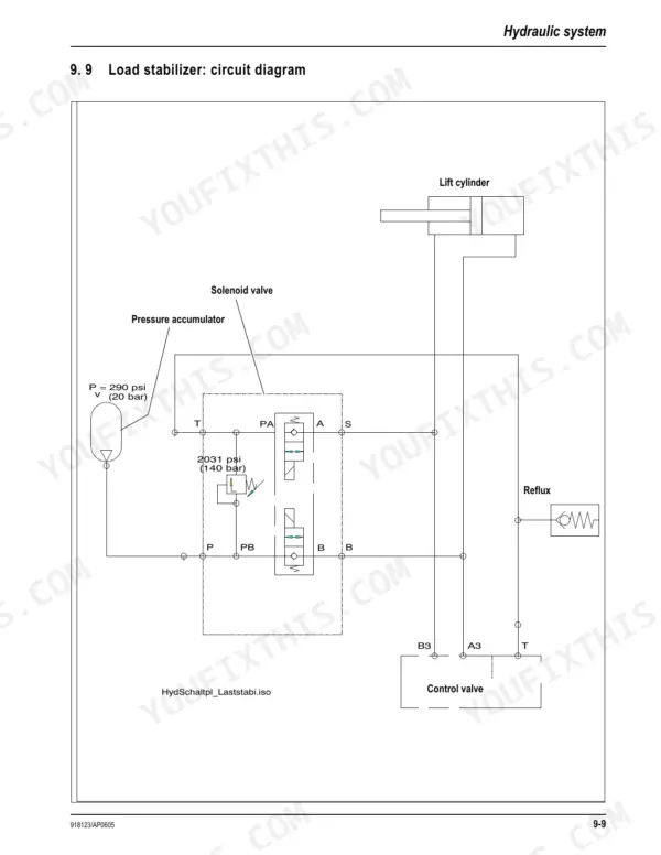
The content is organized into operation, specifications, maintenance, engine, power train, axles, brakes, steering, hydraulic system, electrical system, and torque specifications. It carries fluid capacities, pressure settings, wiring detail, and tightening torques for real repairs.
Owners and independent mechanics use it to service the engine and cooling system, test the hydrostatic power train, work the axles and brakes, adjust the steering circuit, trace wiring faults, and set fasteners to spec. The PDF has a text layer and bookmarks, downloads instantly after purchase, and prints on standard paper.
What's Inside This Manual
| System | Pages | Key Topics |
|---|---|---|
| Operation | 5-14 | Important Information on This Service Manual, Serial Plates and Component Numbers, Machine Overview, Inside of Cab: Overview, Inside of Cab: Legend, Instrument Panel |
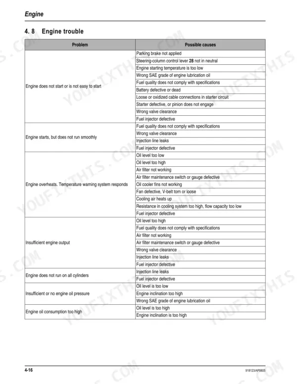
| Engine | 67-84 | Engine BF4M 2011: Overview, Engine Oil Cooling, Fuel System, Checking and Adjusting Valve Tip Clearance, Replacing the Fuel Injection Pump, Setting Charge Air Pressure |
| Power Train | 85-112 | Variable Displacement Pump 12 – 25 Mph, Hydraulic Motor – Control Element 12 Mph, Hydraulic Motor – Hydraulic Connections 12 Mph, Power Train Diagram 12 Mph |
| Axles | 113-134 | Serial Plate – Axle, Front Axle Screw Connections, Rear Axle Screw Connections, Drain, Fill and Check Plug – Front Axle, Fill and Check Plug – Rear Axle |
| Brakes | 135-138 | Brake Circuit, Brake Diagram, Service Brake (Bleeding: Brake System with Bleed Equipment, Inching Valve), Parking Brake Overview (Adjust Brake Lever a) |
| Steering | 139-144 | Steering Circuit, Hydraulic Ports on Servostat, Pressure Relief Valve – Servostat: Settings, Front/Rear Axle Steering Cylinder, Setting the Steering Sensors |
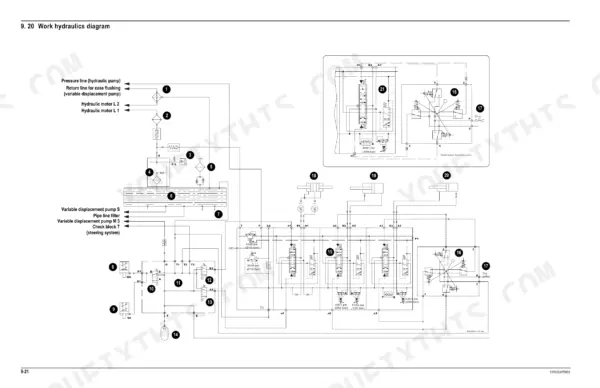
| Hydraulic System | 145-166 | Test Report, Control Valve Connections: Overview, Control Valve: Design, Pilot Control Unit: Design, Valve Block Connections: Overview, Pilot Control Circuit |
| Electrical System | 167-209 | Ohm's Law, Measuring Equipment and Methods, Terminal Description, Cable Color-Coding, Relays, Electrical Units, Fuse Box on Left and Right of Steering Column |
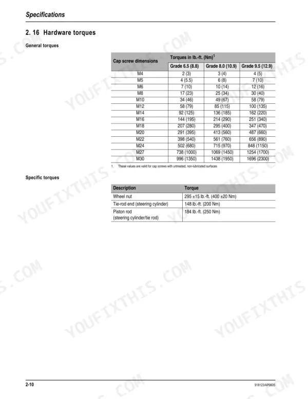
| Torque Specifications | 210-212 | Hydraulic Fittings with Various Seals, With Coarse-Pitch Thread, With Fine-Pitch Thread |
Quick Reference Specifications
| Specification | Value | Page |
|---|---|---|
| Wheel nut torque | 295 ±15 lb.-ft. (400 ±20 Nm) | p. 24 |
| Variable displacement pump displacement | 0 – 5 in.³/rev (0 – 74 cm³/rev) | p. 16 |
| Hydraulic hoses replacement interval | every six years from the date of manufacture | p. 53 |
| Hydraulic oil return filter replacement interval | 1500 service hours (or yearly if you use the machine less than 1500 service hours per year) | p. 51 |
| Battery voltage and capacity | 12-V, 72 Ah | p. 19 |
| Alternator voltage and current | 12-V, 95 A | p. 19 |
| Engine Output | 75 hp (56 kW) at 2300 rpm | p. 15 |
| Max. Engine Torque | 199 lb.-ft. (270 Nm) at 1600 rpm | p. 15 |
| Intake Valve Clearance (cold engine) | 0.01” (0.3 mm) | p. 15 |
| Variable Displacement Pump Max. Operating Pressure | 6527 psi (450 bar) | p. 16 |
| Diesel Engine Oil Capacity | 8.2 qt. (7.8 L) | p. 27 |
| Hydraulic Oil Tank Capacity | About 22 gal. (85 L) | p. 27 |


