Gradall 522, 524, 532C-6, 534C-6 Service Manual (S/N 0177190-0177367) — Wiring Diagrams

$39.99

Model: 522 | 524 | 532C-6 | 534C-6 | 522-3S | 524-3S
Type: Material Handler
Serial: 522 524: 0177190-0177367; 532C-6 534C-6: 0388350-0488237
284 Pages·29 MB·Searchable PDF·English·Print-Ready
  • ✓ Wiring Diagrams
  • ✓ Hydraulic Schematics
  • ✓ Torque Specs
  • ✓ Multi-Level Bookmarks (3-level navigation)
Preview Sample Pages (PDF)
Add to Cart
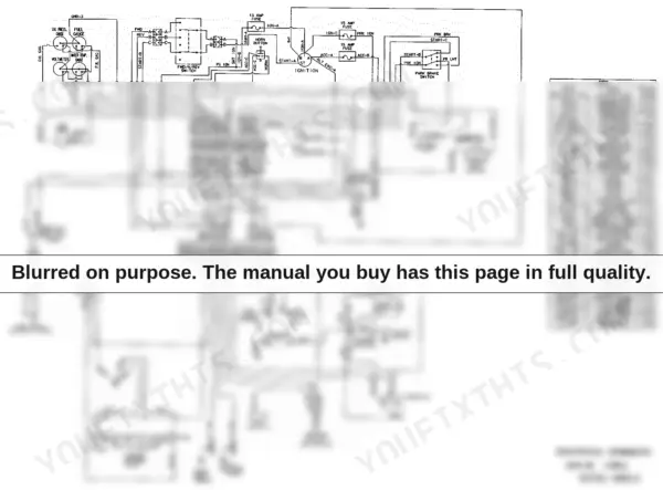
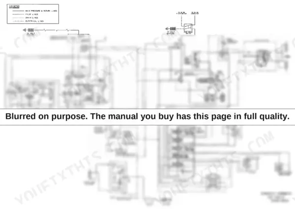
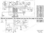
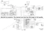
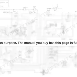
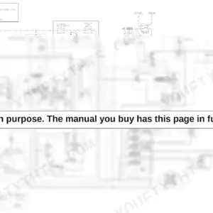
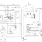
Gradall 522, 524, 532C-6, 534C-6 electrical schematic wiring diagram with wire color key for LPR-60 2WD.
Gradall 522, 524, 532C-6, 534C-6 Service Manual (S/N 0177190-0177367) — Wiring Diagrams
$39.99

Instant Download 24/7

  • Works on PC, Mac, tablet, and phone.
  • Download once, keep forever


Guaranteed Safe Checkout
Visa Mastercard PayPal Apple Pay Google Pay

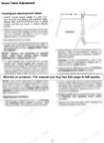
A hydrostatic drive that creeps in neutral or a boom cable gone slack will park a Gradall faster than any engine fault, and this Gradall 534C-6 service manual PDF exists for exactly those days. Factory book 2460-4145 runs 284 pages and covers six variants of the Gradall material handler line. Hydraulic schematics trace the circuits from the Sundstrand M46 pump through the traction lock valve, and wiring diagrams map the full electrical system. Performance checks for the hydrostatic transmission run from charge pressure through the inching valve, each ending in a number you can verify on a gauge. Check for 325 PSI of control pressure in neutral, torque wheel lug nuts to 350-400 lb-ft, and swap hydraulic filters at 1,000 hours. Half these machines outlived the dealers that sold them. Some days it is just you and a dead handler, nobody to call. Download the bookmarked, text-searchable PDF, and by quitting time the boom is swinging again.

Complete the set for your 522-534C-6 Series

What's Inside This Gradall 522-534C-6 Series Manual

SystemPagesKey Topics
Important Safety Notice6
Introduction8General, Operator Qualifications, Orientation
Nomenclature9Fuel Tank, Hydraulic Reservoir, Steering Axle
Safety Highlights10
Decals11-15Optional Equipment Decals
Operators Cab16-17Control & Instrument Identification
Checks & Services Before Starting Engine18
Engine Operation19Starting the Engine, Cold-Weather Starting Aids, Normal Engine Operation
Warm-Up & Operational Checks20Heater, Defroster, Rotating Beacon
Brake System21General, Inching Travel, Service Brakes
Parking the Handler22
Drive Train23
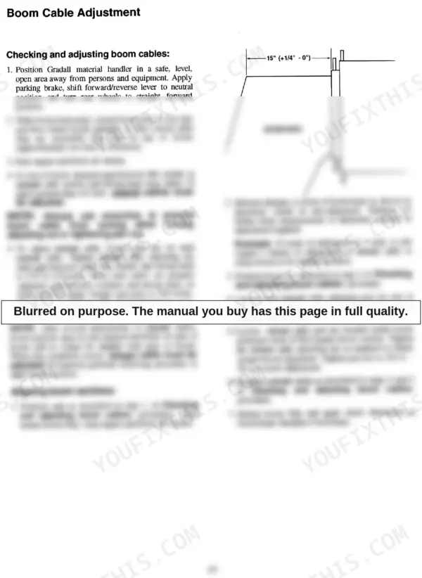
Boom24-25Boom Cable Adjustment
Leveling the Handler26Frame Leveling Lever
Operating Procedure & Techniques27-28Hydraulic Controls, Rated Capacity Chart
Attachments29-31Approved Attachments, Non-Approved Attachments, Carriage/Fork Capacities, Other Attachment Capacities, Attachment Installation, Attachment Operation
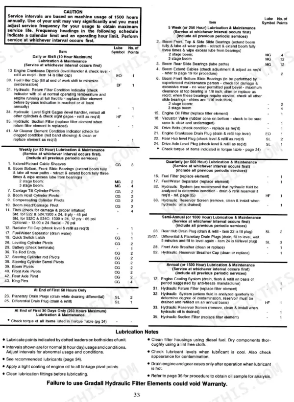
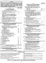
Lubrication & Maintenance Section32-34Lubrication & Maintenance Diagram, Recommended Lubricants & Capacities, Torque Chart
Obtaining Hydraulic Oil Sample for Analysis35-42Test Port, Mini-Check, Hose, Waste Oil Container, Sample Container
Hand Signals and Safety Notices43-46Hand Signals, California Proposition 65 Warnings, Hydraulic Schematic
Hydraulic Component Service Manuals47-74Sundstrand Sauer M46 Pumps and Motors, Rexroth S30 Series Gear Pumps, Mico Power Brake Valve, Auburn Gear Planetary Gear Drive
Meritor Planetary Axle Maintenance75-148Pra 352 Series Planetary Axles, Disassembly, Assembly, Torque Charts, Lubrication Specifications
Gradall Hydrostatic Drive Performance Checks149-174Hydrostatic Transmission Performance, Charge Pressure, Control Pressure, Inching Valve, Hydraulic System Pressures
Boom Maintenance and Adjustment175-250Boom Cable Maintenance, Bearing Pad Adjustment, Boom Section Separation, Crowd Cylinder Removal, Fastener Torque Charts
Implement Circuit Performance Checks251-284Implement Circuit Testing, Steering Circuit, Main Control Valve Relief, Auxiliary Circuit Relief, Donaldson Air Filter Service

Quick Reference Specifications

SpecificationValuePage
Wheel Lug Nuts torque350-400 lb/ft (476-544 N·m)p. 14
Shaft seal installation depth9/64 inch (3.57 mm)p. 51
Hydraulic filter change interval1,000 hoursp. 158
Control pressure325 PSIp. 164
Control pressure test100 PSIp. 164
Charge pressure380-480 PSIp. 161
Drive Circuit (Fwd & Rev) Pressure5,500 ± 100 PSIp. 173
Code 61 4-BOLT Split Flange Bolt Torque (-12 SAE Dash Size)25+/-4.5 ft-lbp. 247
Code 61 4-BOLT Split Flange Bolt Torque (-16 SAE Dash Size)31+/-4.5 ft-lbp. 247
Filter change interval1000 hoursp. 258
Fuel Tank Capacity38 gal.p. 40
Hydraulic System Capacity45 gal.p. 40
BrandGradall
Model522, 524, 532C-6, 534C-6, 522-3S, 524-3S
Machine TypeMaterial Handler
Manual TypeService Manual
LanguageEnglish
FormatSearchable PDF (Digital Download)
Pages284
File Size29 MB
Manual No.2460-4145
Serial Range522 524: 0177190-0177367; 532C-6 534C-6: 0388350-0488237
Wiring DiagramsYes
Hydraulic SchematicsYes
Torque SpecificationsYes
Bookmarked / IndexedYes