
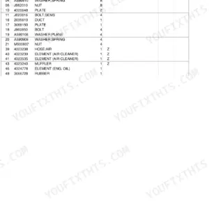
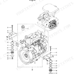
Part of the Hitachi Parts Manuals.
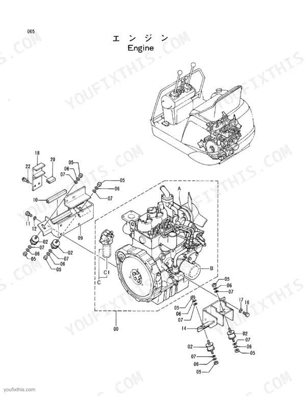
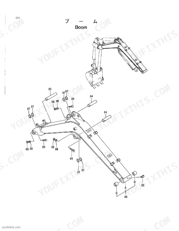
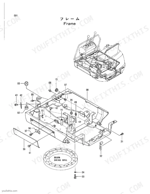
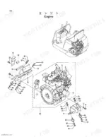
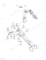
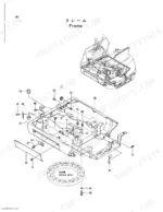
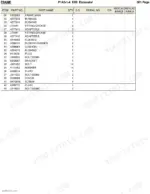
Every part on your Hitachi EX8 mini excavator has a number, and this 185-page Hitachi EX8 parts catalog PDF hands you all of them. Exploded views pair with numbered parts lists for the whole machine: frame, engine, radiator, fuel system, pump device, swing post, travel device, boom, blade, and control levers. You get component-level breakdowns of the gear pump, oil motors, and control valve bodies down to individual spools, springs, seats, and O-rings. Ordering a bucket? All three widths are here (250mm, 300mm, and 340mm), plus standard and long arm assemblies with every pin, bushing, and shim called out. No more describing a part to the dealer over the phone and hoping. Bookmarked with a full text layer; type the component name, jump to the diagram, and order the right piece the first time.
What's Inside This Hitachi EX8 Parts Manual
| System | Pages | Key Topics |
|---|---|---|
| Fuel System | Air Cleaner, Fuel Pipings, Fuel Tank | |
| Cooling System | Radiator, Radiator Support | |
| Engine | Muffler, Lubricate Pipings, Engine Control | |
| Electrical System | Wire Harness | |
| Hydraulics & 3-Point Hitch | Pump Device, Pump;Gear, Valve;Control, Valve-Block | |
| Loader, Backhoe & Attachments | Swing Device, Swing Post, Swing Lock, Boom, Bucket 0.02, Bucket 0.013, Bucket 0.017, Cyl.;Bucket | |
| Body & Operator Station | Frame, Oil Tank, Floor, Seat, Cover, Track Frame, Travel Pipings Cover, Canopy, Pt-Cover | |
| Decals & Accessories | Tool | |
| Other Components | Counterweight, Low Pressure Pipings, Main Pipings, Control Lever, Control Pedal, Lever Lock, Lever Link Parts, Lever Link, Control Box, Electric Parts, Travel Device, Front Idler, Adjuster, Lower Roller, Rubber Crawler, Center Joint |
Hitachi EX8 Common Problems This Manual Covers
Hitachi EX8 bucket pin and bushing part numbers, not sure which bucket the machine came with
Measure the bucket cutting width before ordering anything. The 340 mm (0.02 m3) bucket parts list is on page 116, the 300 mm (0.017 m3) bucket on page 126, and the 250 mm (0.013 m3) bucket on page 124. Match your width to the correct list, then pull the pin and bushing callouts from that exploded view.
Manual Section: Bucket 0.02 (340Mm Wide) p. 116Leaking boom, arm, and bucket cylinders, need to identify seal components from the exploded views
Check the cylinder breakdowns on pages 178 through 184; the bucket cylinder has its own view on page 182. Confirm your front group first, since the standard arm list on page 114 and long arm list on page 122 carry different pins and bushings. Measure the bucket width (250 mm, 300 mm, or 340 mm) to verify which configuration you have, then match callout numbers to the parts list.
Manual Section: Hydraulic Cylinders p. 182Rubber track keeps derailing, need idler, roller, and crawler assembly part numbers
Check the front idler exploded view on page 94 for the idler assembly, axle, ball bearing, seal, and yoke callouts. Inspect the track adjuster breakdown on page 96 for the cylinder, piston rod, dust seal, and grease valve. The lower roller assembly with shaft, bearing, and retaining ring is on page 98, and the rubber crawler shoe assembly is listed on page 100. Record your serial number from the machine name plate before ordering.
Manual Section: Front Idler p. 94Control valve spool sticking, need the right spool, spring, and seal callouts for one section
Identify which valve section you are working on first. The complete control valve assembly with body, Pt-cover, studs, and washers is on page 152, then the nine individual body breakdowns run from page 154 through page 170 with spool, spring, cover, and plunger callouts. Check page 172 for the Pt-cover relief valve, plunger, and O-ring listings, and page 176 for the valve block with ball, seat, shim, and plug. Count sections from the inlet end to match your body number.
Manual Section: Control Valve p. 152Gear pump coupling wobble, need pump, oil seal, and rubber coupling part identification
Check the pump device exploded view on page 20 for the gear pump, pump cover, oil seal, coupling, and rubber coupling callouts. Inspect the rubber coupling elements for cracking before you order; a chewed coupling usually takes the oil seal with it, so pull both callout numbers from the same list. Verify the internal pump components (body, gear, plate, seal, ring, dowel pin) against the gear pump breakdown on page 140 if you are rebuilding rather than replacing.
Manual Section: Pump Device p. 20Frequently Asked Questions
What is the torque specification for the main frame bolts on the Hitachi EX8?
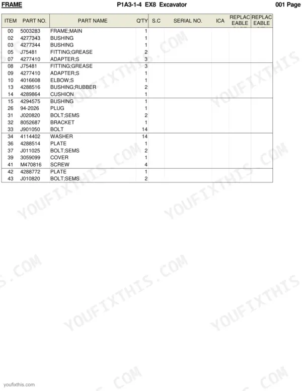
The main frame is secured using 14 bolts (part number J901050) and 14 washers (part number 4114402). While specific torque values are not listed in the table, these 14 bolts are the primary fasteners for the main frame assembly. p. 2
What is the correct fuse rating for the fuse box on the Hitachi EX8?
The fuse box (part number 4280430) contains two types of fuses. It uses three 5A fuses (part number 4164129) and one 15A fuse (part number 4127781). p. 76
How many bolts are used to secure the travel device sprocket?
The travel device sprocket (part number 2032065) is secured using 17 socket bolts (part number M341025). p. 92
What is the part number for the main engine belt on the Hitachi EX8?
The fan belt for the engine is part number 4294837. p. 6
What is the quantity of bolts required to secure the track frame to the swing circle bearing?
The track frame is secured to the swing circle bearing (part number 4270256) using 18 bolts (part number J931050). p. 90
How will I receive this Hitachi EX8 Parts Catalog?
Immediate download of the complete 185-page searchable Parts Catalog. Access it on any device, from a laptop at your desk to a phone in the field.
Can I print specific sections of this Hitachi EX8 Parts Catalog?
Yes. Print a chapter or just the pages for the job at hand, for use in your own shop. Any home or office printer works.


Reviews
There are no reviews yet.