
Wrenching on an Iseki TG5330, TG5390, or TG5470? This 409-page Service Manual PDF walks you through the whole tractor, from HST and transmission teardown to cabin A/C refrigerant charging. Inside: complete wiring circuits with connector pinouts, full hydraulic schematics with circuit illustrations, digital panel check modes with monitor signal countermeasures, and page after page of disassembly procedures for the clutch, front axle, and rear differential. Set clutch pedal free play to 20-30 mm at the pedal top, and hold brake pedal free play at 30 mm before the machine leaves your shop. Chasing an electrical gremlin through a power shift harness without a factory diagram is a losing game. Bookmarked, keyword-searchable, and readable on any device; download it, walk out to your tractor, and fix it right.
What's Inside This Iseki TG5330, TG5390, TG5470 Manual
| System | Pages | Key Topics |
|---|---|---|
| Total Contents | 1-12 | Foreword, Total Contents (Chapter List for the Tractors and Engines Manuals), Table of Contents |
| Introduction | 13-20 | Tractor Types and Punched Identification Marks (Model Name Plate, Chassis Production Number, Engine Model and Serial Number) |
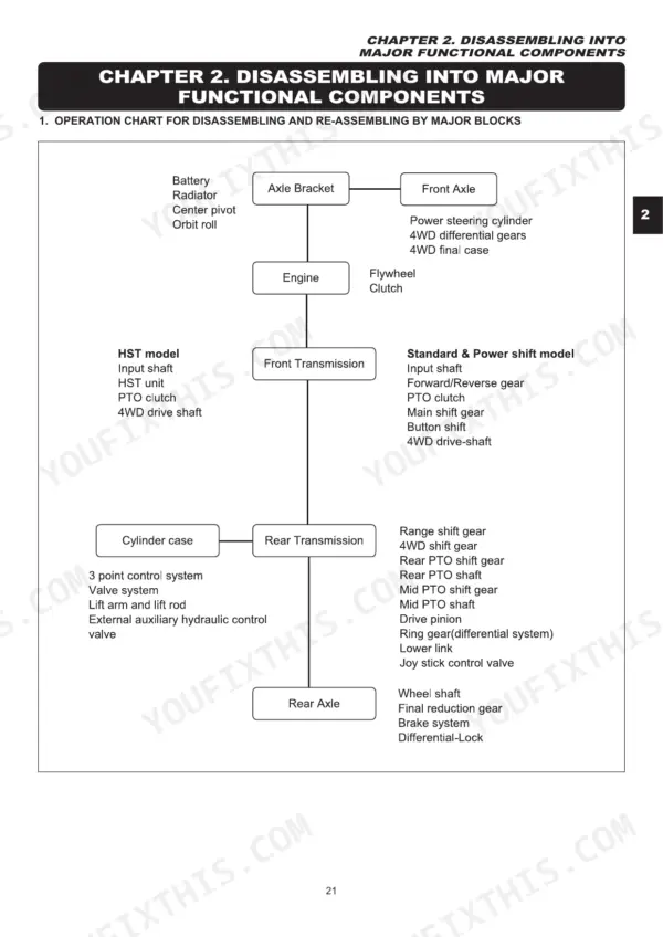
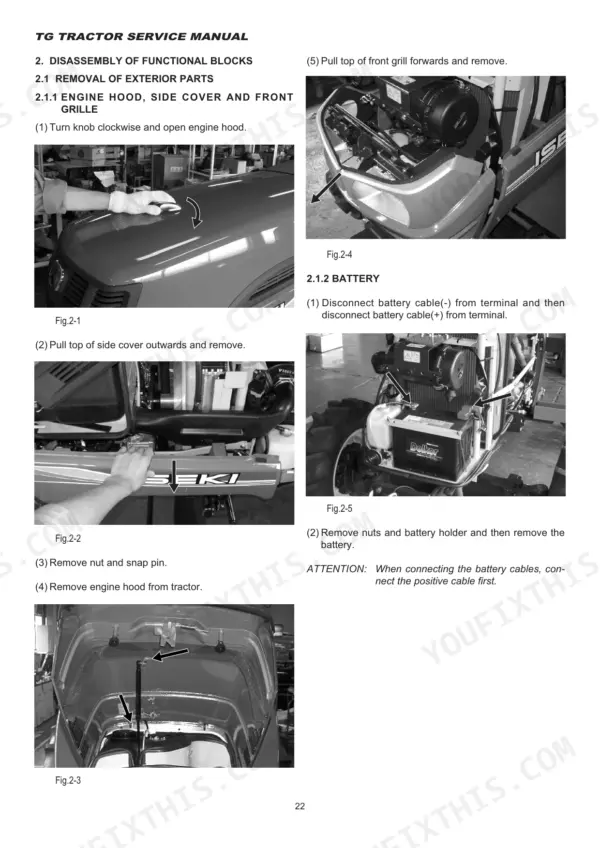
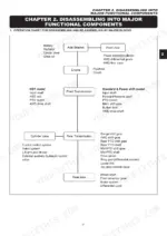
| Disassembling Into Major Functional Components | 21-32 | Disassembly of Functional Blocks |
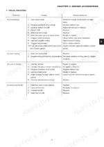
| Engine Accessories | 33-38 | Fuel System |
| Clutch System | 39-44 | Inspection, Precautions for Re-Assembly |
| Transmission | 45-62 | Transmission Construction, Power Train System, Disassembly |
| Rear Axle and Brakes | 63-70 | Rear Axle Housing and Differential Gears, Brakes |
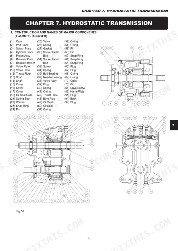
| Hydrostatic Transmission | 71-92 | Operation Diagram of HST, Function, Disassembly and Reassembly, HST Control Pedals and Lever |
| Front Axle | 93-100 | Construction, Disassembly, Precautions |
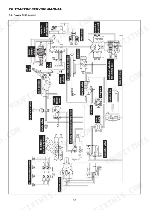
| Hydraulic System | 101-176 | Major Component, Hydraulic Circuit, Illustration for Hydraulic Circuit, General Description, Position Control Link & Lever, Joystick Link & Lever, Troubleshooting |
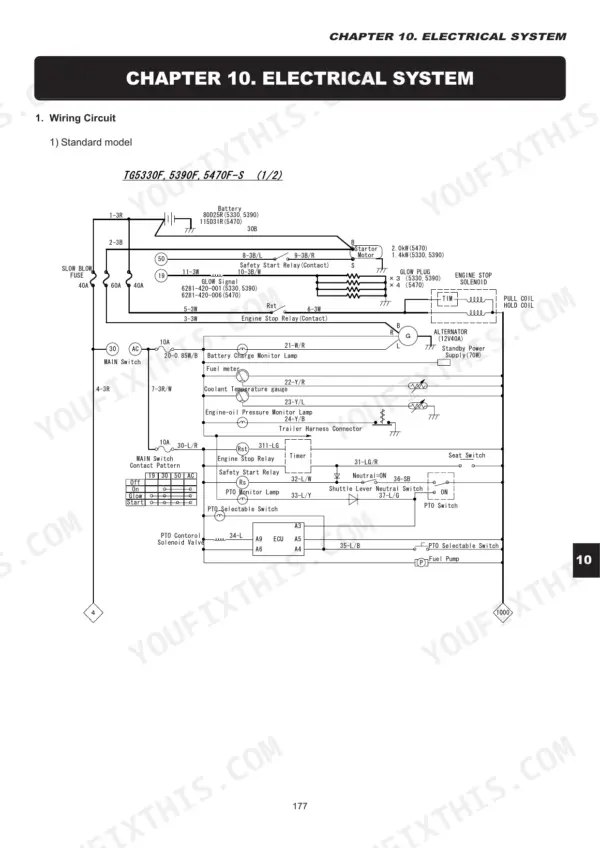
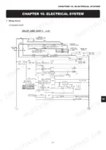
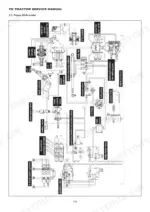
| Electrical System | 177-234 | Wiring Circuit, Instrument Panel (Standard Model), Switch, Relay, Sensor and Solenoid Valve, Sensor, Solenoid Valve, PTO Control System |
| Digital Panel | 235-266 | Digital Panel Indication, Check Mode, Countermeasures for Monitor Signal, Switch and Sensor |
| Cabin | 267-296 | Structure, Operation, And Control, Check and Maintenance, Refrigerant Charging, Troubleshooting |
| Special Tools | 297-300 | TOOL/CLUTCH/PIN Set, TOOL/SHAFT/PTO Set, TOOL/CHECK/PRESSURE/ENGINE, TOOL/SHIFTER, ADAPTER/RELIEF Valve, TOOL/HST Comp |
| Wiring Harness | 301-308 | Power Shift Model |
| Engines Introduction | 309 | Purpose and Scope of the Engines Service Manual, Engines Covered (E3CD, E3CDT, E4CG), Service Precautions and Disclaimer |
| Engines General Information and Specifications | 313-318 | Exterior Views & Identification Numbers |
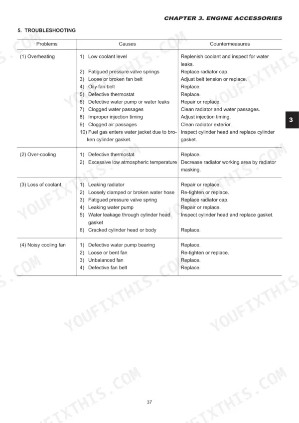
| Engines Service Standards | 319-334 | Service Standards, Troubleshooting |
| Engines Inspection and Adjustment | 335-370 | Inspection and Adjustment, Engine Body |
| Engines Lubrication System | 371-376 | General Description, Removal, Disassembly, Inspection and Re-Installation of Oil Pump |
| Engines Cooling System | 377-378 | Cooling System Diagram, Thermostat, Water Pump |
| Engines Fuel System | 379-390 | Removal, Disassembly, Inspection, Re-Assembly, And Installation, Injection Nozzles and Holders, Governor |
| Engines Electrical System | 391-409 | Starter, Alternator |
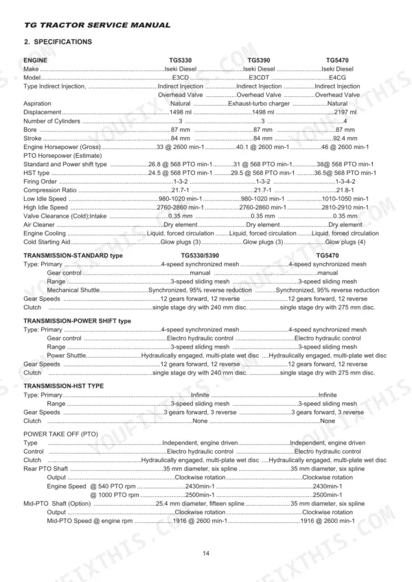
Quick Reference Specifications
| Specification | Value | Page |
|---|---|---|
| All Models | ||
| free play of brake pedal | 30mm | p. 67 |
| Valve Clearance (Cold);Intake | 0.35 mm | p. 14 |
| TG5330 | ||
| Engine Horsepower (Gross), TG5330 | 33 @ 2600 min-1 | p. 14 |
| TG5390 | ||
| Engine Horsepower (Gross), TG5390 | 40.1 @ 2600 min-1 | p. 14 |
| TG5470 | ||
| Engine Horsepower (Gross), TG5470 | 46 @ 2600 min-1 | p. 14 |
| Displacement, TG5470 | 2197 ml | p. 14 |
| Engine Crankcase with Filter Capacity, TG5470 | 8.0 liters | p. 15 |
| TG5330/5390 | ||
| Displacement, TG5330/5390 | 1498 ml | p. 14 |
| Engine Crankcase with Filter Capacity, TG5330/5390 | 4.7 liters | p. 15 |
| Transmission Fluid Capacity | 31.0 liters | p. 15 |
Iseki TG5330, TG5390, TG5470 Common Problems This Manual Covers
Iseki TG5330 clutch slips under load in high gears, pedal engagement point near the floor
Measure clutch pedal free play at the pedal top and adjust the linkage until you get 20-30 mm, the spec on page 42. If free play is correct and the clutch still slips, split the tractor and inspect the disc for glazing, oil contamination, and worn facings following the inspection steps starting on page 39.
Manual Section: Clutch System p. 42Gears grind going into forward or reverse even with the clutch pedal pressed to the floor
Check pedal free play first; anything past 30 mm at the pedal top means the clutch never fully releases, so bring it back into the 20-30 mm range on page 42. If grinding continues, inspect the release bearing and fork for wear and follow the re-assembly precautions in the Clutch System section starting on page 39.
Manual Section: Clutch System p. 42Brake pedals grab unevenly and the tractor pulls hard to one side when stopping
Adjust free play on each brake pedal to 30 mm so both sides engage together, using the procedure in the Rear Axle and Brakes section starting on page 63. Verify the pedal latch is connected before any road travel. If one side still drags or grabs, pull the brake covers and inspect the discs for uneven wear.
Manual Section: Rear Axle and Brakes p. 67Engine hard to start and runs rough with poor output under load at working speed
Bleed the fuel system, confirm clean fuel delivery, and replace clogged filters before condemning the injection pump. Then work through the no-start and poor-output charts in the service standards on page 319. With the engine cold, check valve clearance and set the intake valves to 0.35 mm using the adjustment procedure starting on page 335.
Manual Section: Engines Service Standards p. 319Frequently Asked Questions
What are the recommended service intervals?
Transmission oil and filter should be changed after the first 50 hours of operation and then every 200 hours. The Service Interval Alarm will illuminate when the hour meter reaches 50, 100, 200, 300, or 400 hours, indicating that service is required. A detailed maintenance table on page 273 provides intervals for various components, including daily, weekly, yearly, and every 2 or 8 years checks. p. 114
What fluids and capacities does this machine require?
The machine requires various fluids with specific capacities depending on the model. For TG5330/5390, the engine crankcase with filter capacity is 4.7 liters, transmission is 31.0 liters, fuel tank is 40.0 liters, cooling system is 6.7 liters, and front drive axle (4WD Only) is 7.5 liters. For TG5470, the engine crankcase with filter is 8.0 liters, transmission is 38.0 liters, fuel tank is 50.0 liters, cooling system is 7.6 liters, and front drive axle (4WD Only) is 8.5 liters. The air conditioner uses R134a refrigerant and ND-OIL8 lubricant (60 cm3). p. 15
How to troubleshoot engine won't start?
To troubleshoot an engine that won't start, first check the starter. If the starter does not work, check the battery charge and wiring. If the starter works but the engine does not start, inspect the fuel system, including the fuel pump fuses, fuel filter, and air-bleeding. Also, check the glow plug control resistor and normal glow plug control resistor. p. 328
What are the valve clearance specifications?
The specified valve clearance (cold) for both intake and exhaust valves is 0.35 mm (0.0137 in.) for all engine models (E3CD, E4CG). This clearance should be adjusted using a feeler gauge and the adjusting screw. p. 336
What torque specifications are listed?
Various torque specifications are provided for different components. For the clutch system, flywheel bolts should be tightened to 910-1070 kgf·cm, and clutch assembly bolts to 240-310 kgf·cm. In the hydraulic system, the main relief valve tightening torque is 63.8±0.5 Nm (650±50 kgfcm), and the gear shifting valve solenoid is 5.4±0.5 Nm (55±5 kgfcm). Engine cylinder head bolts are tightened to 6.5 - 7.0 kgf·m (46.9 - 50.6 ft·lbs). p. 327
Is this Iseki TG5330 manual a download or a disc?
A 409-page Service Manual in searchable PDF format, available the moment you complete checkout. View on computer, tablet, or phone, with no shipping wait.
Am I free to print this Iseki TG5330 Service Manual?
Yes, print as many copies as you want, and there are no restrictions. Many mechanics print the section they need and bring it to the shop floor.


Reviews
There are no reviews yet.