
Part of the JCB Repair Manuals.
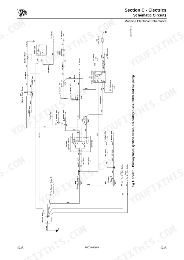
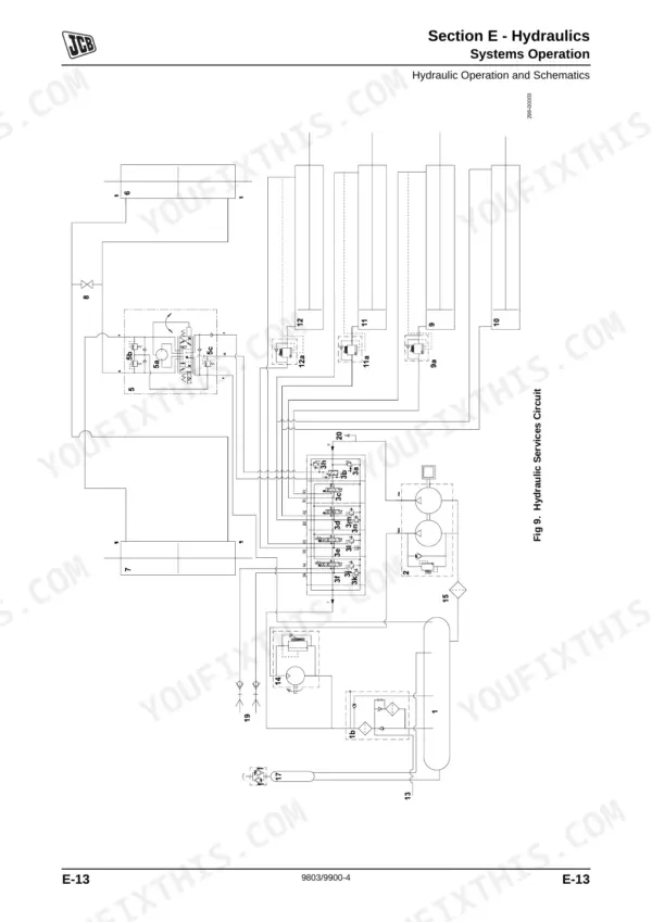
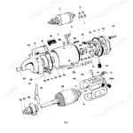
Hydrostatic drive is the hardest system to get right on a JCB 515-40 Loadall telehandler, and this 641-page JCB 515-40 service manual PDF (publication 9803/9900-4) takes you through the transmission pump and wheel motors before widening out to the boom, load moment indicator, brakes, steering, and both the Deutz and Kohler engines. Wiring schematics trace each circuit through the alternator, starter motor and harness, and the hydraulic chapter pairs a schematic symbols key with the main services pump, control valve block and rams. Service schedules, fluids and greasing points take up a long stretch of the book. Expect 80A nominal from the alternator (82A maximum) when you test the charging circuit, and torque a 3/8 in. BSP hose to 33.0 to 40.0 Nm. A guessed hose torque is how a fitting lets go under boom load. Bookmarked and text-searchable, the download travels with you to the yard, the site cabin, or wherever your Loadall is parked.
What's Inside This JCB 515-40 Manual
| System | Pages | Key Topics |
|---|---|---|
| General Information | 1-47 | Introduction, Machine Identification, Standard Torque Settings, Service Tools, Service Consumables, Colour Coding |
| Care and Safety | 48-67 | Safety Notices, Safety Check List, Safety Labels, General Safety, Maintenance Safety |
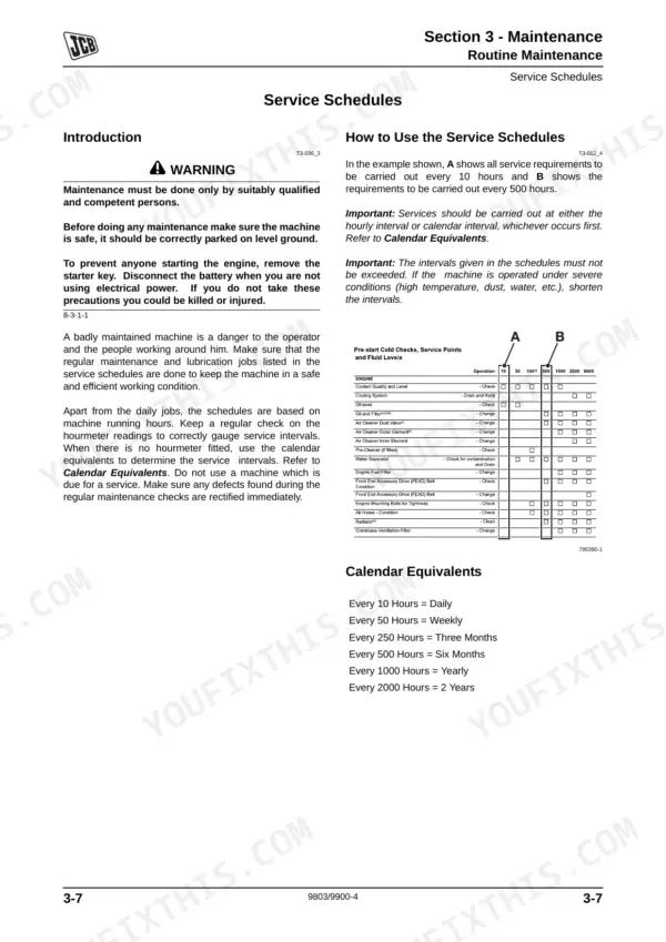
| Maintenance | 68-167 | Service Schedules, Fluids and Lubricants, Cleaning, Checking for Damage, Greasing, Oiling |
| Attachments | 168-175 | Connecting Hydraulic Hoses, Disconnecting Hydraulic Hoses, Quick Release Couplings |
| Body and Framework | 176-275 | Load Moment Indicator, Cab Heating and Ventilation, Air Conditioning, Glazing, Boom, Counterweight |
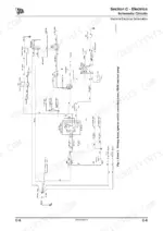
| Electrics | 276-355 | Schematic Circuits, Multimeter Usage, Alternator, Starter Motor, Battery, Harness Data |
| Controls | 356-369 | Manual Control Levers, Joystick, Control Assembly, Control Rod Assembly |
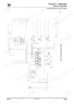
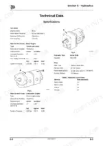
| Hydraulics | 370-441 | Hydraulic Schematic Symbols, Main Services Pump, Control Valve Block, Rams, Hydraulic Tank |
| Transmissions | 442-509 | Hydrostatic Transmission, Transmission Pump, Wheel Motors, Wheels and Tyres |
| Brakes | 510-541 | Service Brakes, Park Brake, Brake Shoes, Brake Wheel Cylinder, Brake Master Cylinder |
| Steering | 542-573 | Hydraulic Steer Unit, Priority Valve, Steer Ram, Steer Stops, Re-Phasing Wheels |
| Engine | 574-641 | Deutz Engine, Kohler Engine, Engine Sensors, Cooling Pack, Throttle Cable, Fuel System |
Quick Reference Specifications
| Specification | Value | Page |
|---|---|---|
| BSP Hose Torque (1/8 in.) | 14.0 - 16.00 Nm | p. 23 |
| BSP Hose Torque (1/4 in.) | 24.0 - 27.0 Nm | p. 23 |
| Hydraulic filter cap torque | 20 Nm (14.7 lbf ft) | p. 165 |
| Alternator Maximum output | 82A | p. 282 |
| Alternator Nominal output | 80A | p. 282 |
| Battery voltage | 12 volts | p. 282 |
| Maximum charging voltage | 15.8 Volts | p. 300 |
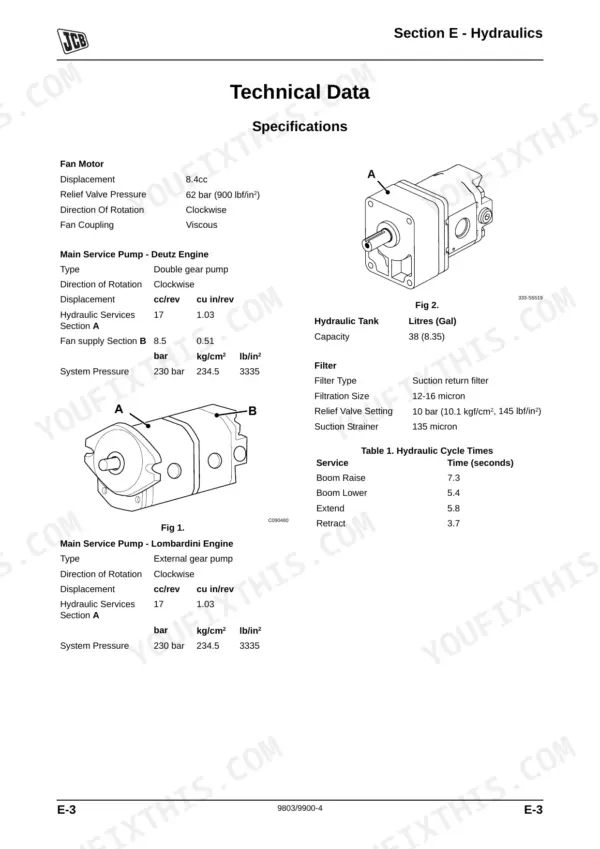
| Filtration Size | 12-16 micron | p. 376 |
| Suction Strainer | 135 micron | p. 376 |
| Fan Motor Relief Valve test pressure | 0 - 100 bar (0 - 1450 lbf/in2) | p. 413 |
| Torque for piston head 40-6 | 405 Nm (41 Kgf m, 300 lbf ft) | p. 435 |
| Deutz Engine Oil Capacity | 8.0 (1.76) Litres (Gal) | p. 85 |
JCB 515-40 Common Problems This Manual Covers
JCB 515-40 main hydraulic services lack power and rams are slow to operate
Check the main relief valve operating pressure against 230 bar (3336 lbf/in2) listed in the hydraulic specifications on page 376. Inspect the suction strainer, rated at 135 micron, and the 12-16 micron filtration for blockage before suspecting the main services pump. Work through the lack of power and slow ram checks in the Main Hydraulic Services fault chart.
Manual Section: Main Hydraulic Services FaultsMain hydraulic rams creep when holding a load with the controls released
Inspect each ram and its hose connections for external leakage, then tighten BSP hose fittings to the page 23 torque range for their size, such as 33.0 to 40.0 Nm for 3/8 in. If a ram must be stripped, torque the piston head to 405 Nm and end cap to 678 Nm following page 435.
Manual Section: Main Hydraulic Services FaultsHydrostatic transmission pump drives one way but does not work in the other direction
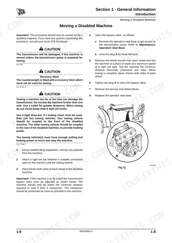
Verify whether drive is lost in one direction or both, since the Transmission Pump fault charts treat these separately from the neutral fault. Inspect pump and wheel motor connections for hydraulic leaks, then test whether each wheel motor revolves or runs sluggish, following the Transmissions section from page 442.
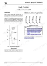
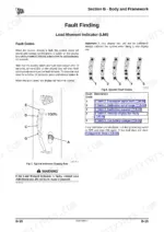
Manual Section: Transmission Pump FaultsLoad moment indicator shows transducer signal fault or calibration required warning on the display
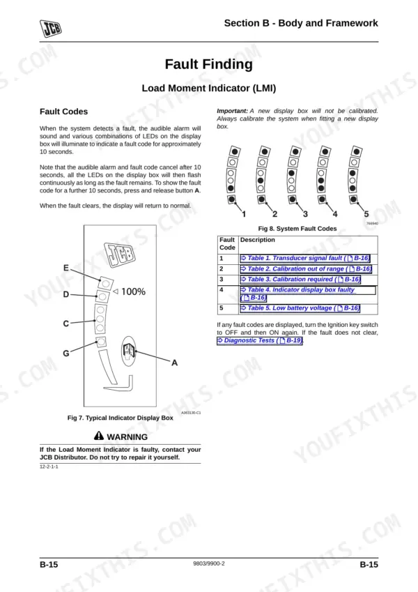
Check battery condition first, because low battery voltage is one of the listed LMI fault causes; battery voltage is 12 volts per page 282. Inspect the transducer and its connection for a signal fault, then run the calibration following the LMI fault pages starting. Replace the display box only after those checks pass.
Manual Section: Load Moment Indicator (LMI) FaultsService brakes not releasing after the brake pedal is let off, or excessive pedal travel
Check the brake fluid level first; the braking system holds only 1 litre (0.22 gal) per page 85, so a small loss shows quickly. Inspect the master cylinder and each wheel cylinder for leaks or sticking, then check brake shoe condition and adjustment against the Brake System fault chart before road testing.
Manual Section: Brake System FaultsFour wheel steer out of phase, with the steering wheel turning on its own
Check the hydraulic steer unit and priority valve before chasing the rams if the steering wheel turns on its own. For a 4WS phasing fault, re-phase the wheels following the Steering section from page 542, then inspect the steer ram and verify the steer stops are set correctly.
Manual Section: Steering System FaultsFrequently Asked Questions
What causes low hydraulic power on a JCB 515-40?
Low hydraulic power can be caused by insufficient hydraulic fluid, hydraulic leaks in the system, poor engine performance, an incorrect MRV setting, or low pump flow. To troubleshoot, check for leaks and top up fluid, check hoses, check engine performance, check and adjust the MRV setting, or check for external leaks and priority valve sticking. p. 406
How do I diagnose a transmission fault on the JCB 515-40?
To diagnose transmission faults, first ensure the hydraulic oil is clean and filled to the correct level. Use the fault tables provided in the manual to identify the problem, such as 'Transmission will not go into neutral' (Table 3), 'Low system efficiency' (Table 4), 'Transmission does not work in either forwards or reverse' (Table 7), or 'Transmission does not work in one direction only' (Table 8). p. 470
What are the fuel filter replacement specifications for the JCB 515-40?
The fuel filter should be changed at the intervals specified in the Service Schedules. If the engine is difficult to start or has poor performance, fit new filters. For the Deutz engine, the fuel filter is changed as part of the routine maintenance procedure. p. 142
What is the torque setting for the Deutz engine alternator fixing bolt on the JCB 515-40?
The torque setting for the Deutz engine alternator fixing bolt is 40 Nm. p. 582
What is the capacity of the hydraulic tank on the JCB 515-40?
The hydraulic tank has a capacity of 38 liters (8.35 gallons). p. 376
How is this JCB 515-40 Service Manual delivered?
Immediate download of the complete 641-page searchable Service Manual. Access it on any device, from a laptop at your desk to a phone in the field.
Am I free to print this JCB 515-40 Service Manual?
Yes. It prints from any PDF reader, so run off the pages you need for your own repair work.


Reviews
There are no reviews yet.