Part of the John Deere Repair Manuals.
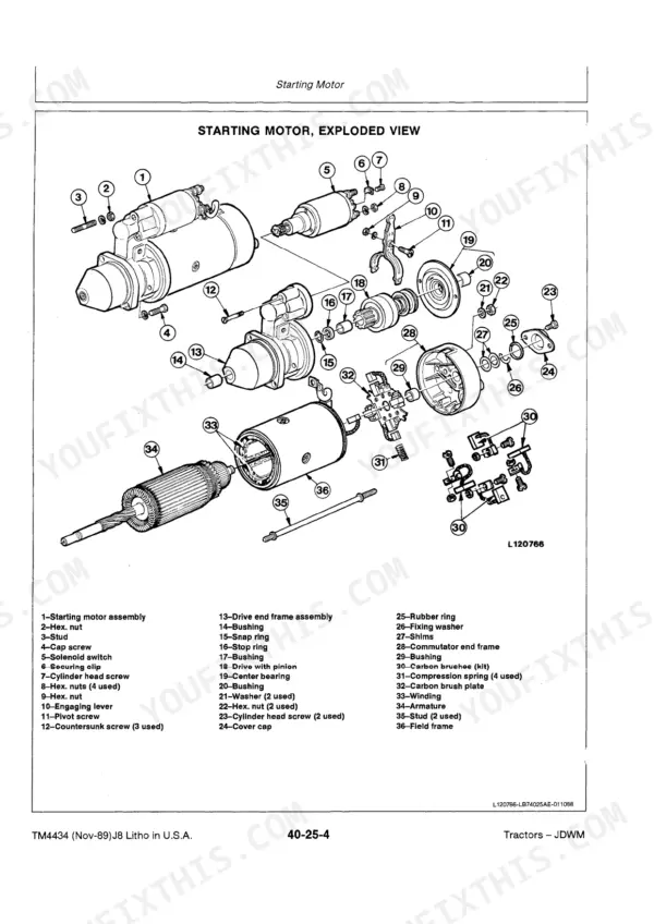
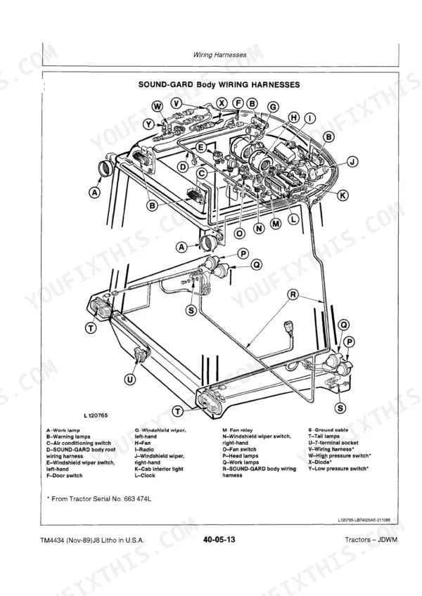
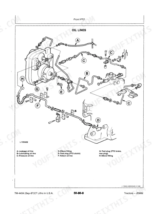
Need the factory service data for your John Deere 2355? This 839-page John Deere 2355 technical manual PDF (OEM TM4434) also covers the 2555, 2755, and 2855N tractors, from engine and clutch through power train, steering, hydraulics, and the Sound-Gard cab. Inside: wiring harness diagrams for every serial number break, hydraulic schematics, a dedicated troubleshooting section, and torque tables for hardware across all systems. You get step-by-step teardown and rebuild procedures for the clutch, Hi-Lo shift unit, hydrostatic steering, and hydraulic pumps. Set hydraulic stand-by pressure to 16000 kPa (2320 psi) and hold pump shaft end play between 0.1 and 0.9 mm before you button it up. No more chasing wiring faults with a multimeter and a prayer. Bookmarked by section; load it on any device and take it straight to the shop floor.
What's Inside This John Deere 2355, 2555, 2755, 2855N Manual
| System | Pages | Key Topics |
|---|---|---|
| Safety | 4-11 | Safety and You, Important, Notes, Observe Safety Rules, Prepare for Emergencies, Handle Fluids Safely – Avoid Fires, Prevent Battery Explosions, Prevent Acid Burns |
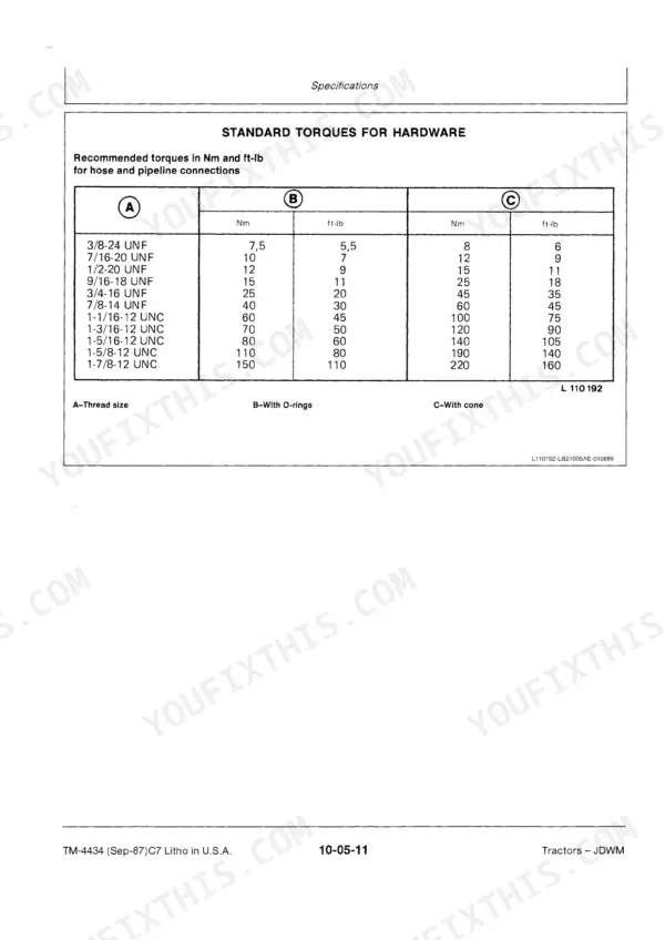
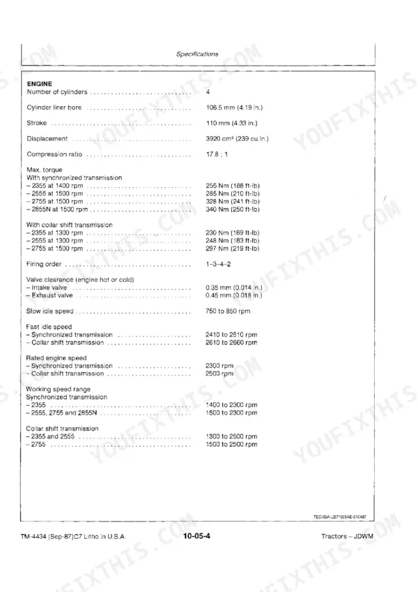
| General | 12-207 | Specifications (Serial Number Plates, Product Identification Number, Engine Serial Number, Transmission Serial Number, Front Wheel Drive Axle Serial Number, Sound-Gard Body Serial Number, Model Serial Numbers, Engine, Engine Clutch, Cooling System, Fuel System, Electrical System, Synchronized Transmission, Collar Shift Transmission, Hi-Lo Shift Unit, Reverser Transmission, Creeper Transmission, Differential and Final Drives, Differential Lock, Independent PTO, Continuous-Running PTO, PTO Speeds, Front PTO, Front Wheel Drive, Hydrostatic Steering, Power Steering, Hydraulic Brakes, Handbrake, Hydraulic System, Rockshaft, Ground Travel Speeds, Front and Rear Wheels, Dimensions and Weights, Capacities, Standard Torques for Hardware) |
| Engine | 208-215 | Radiator, Viscous Fan Drive and Fan, Torques for Hardware, Special Tools, Draining Coolant, Removing Air Intake Line, Removing Bottom Coolant Hose, Removing Top Coolant Hose |
| Fuel and Air Intake System | 216-231 | Fuel Tank |
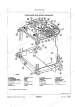
| Electrical System | 232-303 | Wiring Harnesses (Special Tools, Specifications, Disconnecting Electrical Circuit, Engine Wiring Harnesses, Dash Wiring Harness – Without Sound-Gard Body, Dash Wiring Harness – Gp Tractors Without Sound-Gard Body, Dash Wiring Harness – with Sound-Gard Body, Disconnecting Point – Transmission Wiring Harness, Transmission Wiring Harness – Without Sound-Gard Body, Transmission Wiring Harness, Disconnecting Point – Cab Wiring Harness, Fender Wiring Harnesses, Front PTO Wiring Harness) |
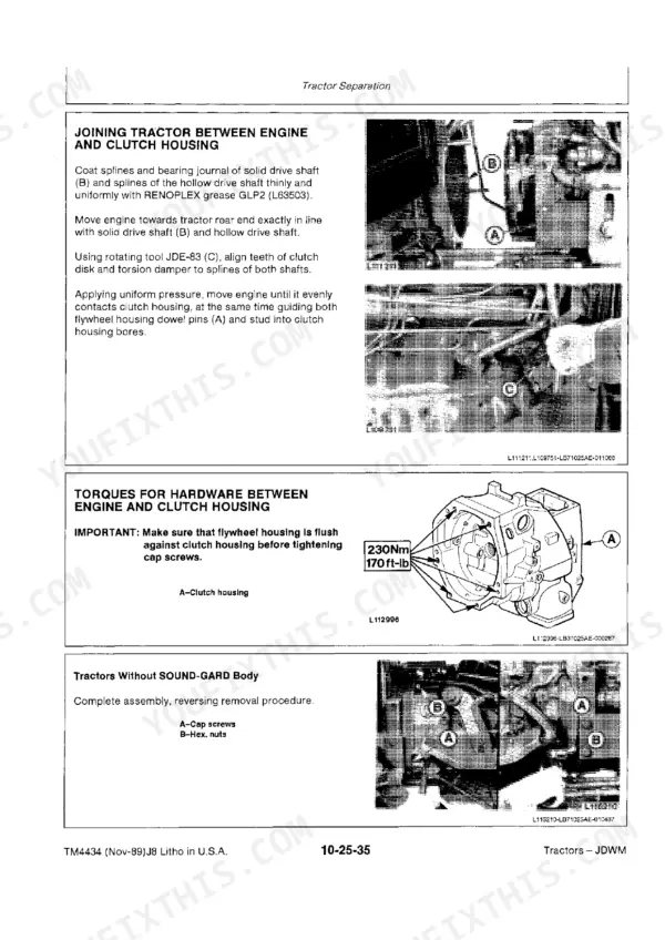
| Power Train | 304-563 | Clutch Operating Systems (Specifications, Torques for Hardware, Hydraulically Operated Clutch, Bleeding Clutch Operating System, Removing Dash Panel at Panel Support, Removing Clutch Pedal, Upper Clutch Operating System, Exploded View, Removing Slave Cylinder, Slave Cylinder, Sectional View, Removing Throw-Out Bearing, Removing Ring Piston, Removing Guide Sleeve, Repairing Clutch Slave Cylinder, Installing Slave Cylinder, Master Cylinder, Rear Stop Screw, Preliminary Adjustment of Piston Rod Clearance, Preliminary Adjustment of Front Stop Screw, Filling System with Brake Fluid) |
| Steering System and Brakes | 564-624 | Hydrostatic Steering, Special Tools, Specifications, Torques for Hardware, Removing Steering Wheel, Removing Metering Unit Cover, Removing Suction Valves |
| Hydraulic System | 625-730 | Valves, Specifications, Torques for Hardware, Cm³ Hydraulic Pump, – Hydraulic Pumps, Removing By-Pass Valve of Transmission Oil Filter, Installing By-Pass Valve |
| Miscellaneous | 731-752 | Front Axle, Special Tools, Specifications, Torques for Hardware, Front and Rear Wheels, Removing Front Wheel, Removing Wheel Hub, Front Wheel |
| Operator's Station | 753-839 | Safe Handling of Refrigerants, Safety Precautions, Safety Equipment, Servicing Air Conditioning System, Special Tools, Specifications, Discharging the System, Evacuating the System |
Quick Reference Specifications
| Specification | Value | Page |
|---|---|---|
| Hydraulic stand-by pressure | 16000 kPa (160 bar; 2320 psi) | p. 639 |
| Hydraulic pump shaft end play | 0.1 to 0.9 mm (0.004 to 0.035 in.) | p. 639 |
| Steering wheel to steering shaft torque | 70 Nm (50 ft-lb) | p. 593 |
| Fuel tank capacity | 84.0 L (22.2 U.S. gal.) | p. 26 |
| Auxiliary fuel tank capacity | 52.0 L (13.7 U.S. gal.) | p. 26 |
| Engine oil change interval | Every 100 hours | p. 82 |
| Transmission/hydraulic system service interval | Every 1200 hours | p. 82 |
John Deere 2355, 2555, 2755, 2855N Common Problems This Manual Covers
Engine cranks slowly or will not turn over at all, especially on cold mornings
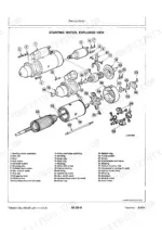
Check battery terminals for corrosion, then clean and tighten the clamps. Load-test the battery; never charge a frozen one, warm it to 16°C (60°F) first per the safety note on page 6. If the battery passes, test voltage drop across the starter circuit and inspect the starting motor and neutral start system in the Electrical System section on page 232.
Manual Section: Electrical System p. 232Three-point hitch lifts slowly and remote valves feel weak, implements creep down under load
Check transmission-hydraulic oil level and top up before anything else, then replace the hydraulic filter, a common cause of sluggish response. If performance stays weak, pull the hydraulic pump and measure shaft end play; without through drive the spec is 0.1 to 0.9 mm (0.004 to 0.035 in.) on page 639. Replace worn thrust washers while the pump is apart.
Manual Section: Hydraulic System p. 639Steering wheel feels loose with excessive free play, front end wanders at road speed
Torque the steering wheel hex nut to 70 Nm (50 ft-lb) per page 593 before condemning anything else. If play remains, verify hydraulic oil level, then inspect the hydrostatic steering metering unit and double-acting shock valves covered in the Steering System and Brakes section starting on page 564. Replace worn metering unit parts as a set.
Manual Section: Steering System and Brakes p. 593Frequently Asked Questions
What are the recommended service intervals?
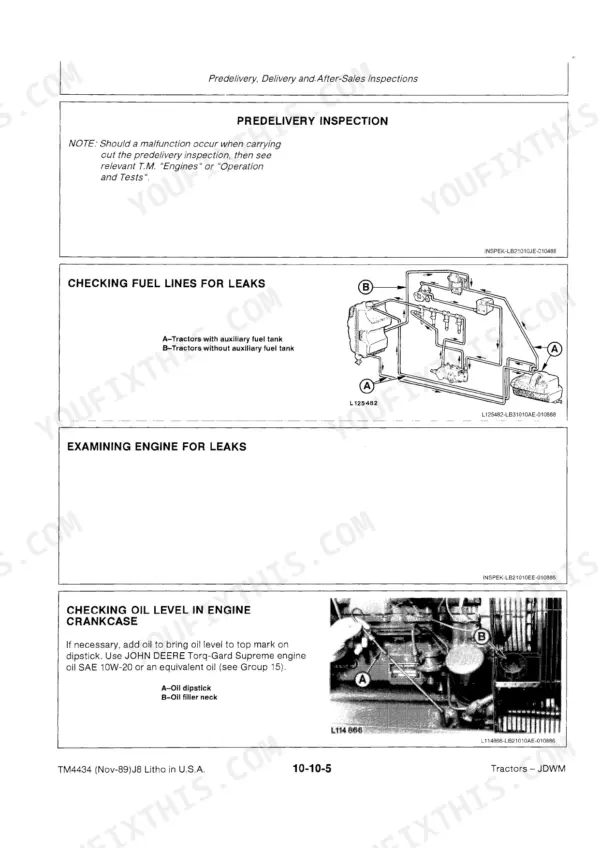
Service intervals vary by component. For instance, engine oil should be changed every 100 hours, while transmission/hydraulic oil has a service interval of every 1200 hours. Lubricating points should be checked predelivery and every 50 hours. p. 82
What fluids and capacities does this machine require?
The fuel tank capacity is 84.0 liters (22.2 U.S. gal.), and the auxiliary tank holds 52.0 liters (13.7 U.S. gal.). The engine crankcase requires 10.5 liters (2.8 U.S. gal.) of oil, and the cooling system without a SOUND-GARD Body needs 13.0 liters (3.4 U.S. gal.) of coolant. Brake fluid should be DOT4. p. 26
How do you fix John Deere 2355 control valve spraying oil mist under pressure, hydraulics losing power?
Replace the O-rings in the control valve spools; Deere upgraded these after the originals disintegrated under pressure. Remove each spool, clean the bores, and install the updated seal kit. After reassembly, test stand-by pressure against the 16000 kPa (160 bar; 2320 psi) spec on page 639 and recheck for misting at full relief. p. 639
How do you fix hydraulic oil leaking near transmission split on right side, puddle forming under shift cover?
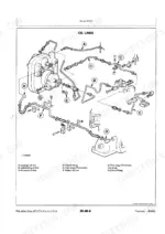
Inspect the steel pipe running from the shift cover to the transmission split, bottom right side; these wear through against the case. Replace the pipe, then refill and recheck the transmission-hydraulic oil level. If the leak source is unclear, trace the circuit on the hydraulic schematic, then confirm the system holds 16000 kPa (160 bar) after repair.
Is this John Deere 2355 manual a download or a disc?
Immediate download of the complete 839-page scanned Technical Manual. Access it on any device, from a laptop at your desk to a phone in the field.
Can I print specific sections of this John Deere 2355 Technical Manual?
Yes. Print the pages or sections you need for your own shop use. Any standard printer works.
Is the hydraulic system diagrammed in this John Deere 2355 manual?
A hydraulic system diagram for the John Deere 2355, 2555, 2755, 2855N is included.