

Part of the John Deere Repair Manuals.
Looking for the John Deere 280 technical manual PDF? This 840-page factory Technical Manual (OEM TM700419) covers the full 280, 284, 300, 304, 320, 324, and B350 tractor line in one download. You get complete electrical schematics with cable color codes and circuit-by-circuit test points, hydraulic system diagrams, exploded views of the clutch, gearbox, differential, final drive, and MFWD, plus metric and imperial torque tables and a full troubleshooting section covering clutch slippage, hard shifting, weak lift, and noisy pumps. Check your battery against the factory 95D31L spec (12V, 85Ah) and confirm the QDJ1308L starter is putting out its rated 3 kW before you condemn a wiring harness. No more chasing electrical gremlins with a multimeter and a prayer. Bookmarked, text-searchable, and ready to pull up on your phone right next to the machine.
What's Inside This John Deere 280-324 Series & B350 Manual
| System | Pages | Key Topics |
|---|---|---|
| General Information | 9-121 | Safety Regulations (Live with Safety, Recognize Safety Information, Understand the Meaning of Sign Words, Follow Safety Instructions, Handle Fluids Safely, Avoid Fires, Prevent Battery Explosions, Handle Batteries Safely, Prepare for Emergencies, Remove Paint Before Welding or Heating, Avoid High-Pressure Fluids, Engine Coolant, Prevent Machine Runaway, Avoid Heating Near Pressurized Fluid Lines, Work in Ventilated Area, Use Starting Fluid Safely, Wear Protective Clothing, Noise Isolation, Service Front-Wheel Driven Tractor Safely, Tighten Wheels-Fixing bolts/nuts, Store Implements Safely, Produce Dealer Self-Made Tools Safely, Use Fuel Safely - Prevent Fire, Practice Safe Maintenance, Stay Away From Rotating Drive Shaft, Use Steps and Handrails Correctly, Operate Tractor Safely, Limited Use for Forestry Operation, Use Loader and Tractor Safely, Keep Riders Off the Machine, Instructor′s Seat, Using Safety Warning Lights and Devices, Use Safety Chains, Transport Towed Implements at Safe Speed, Be Cautious on Slopes and Uneven Terrain, Drag a Machine Out of Mud Pits, Avoid Contact with Pesticides, Handle Pesticides Safely, Handle Global Positioning System Receiver Safely, Stay Away From High-Temperature Radiation, Avoid Tractor Being Out of Control, Transport Tractor Safely, Service the Cooling System Safely, Service the Accumulator System Safely, Park Machine Safely, Use Proper Lifting Equipment, Support Machine Safely, Work in Clean Area, Illuminate Work Area Safely, Service Machines Safely, Use Proper Tools, Service Tires Safely, Safe Servicing of Front-Wheel Drive, Use Seat Belt Properly, Keep ROPS Installed Properly, Dispose of Waste Properly) |
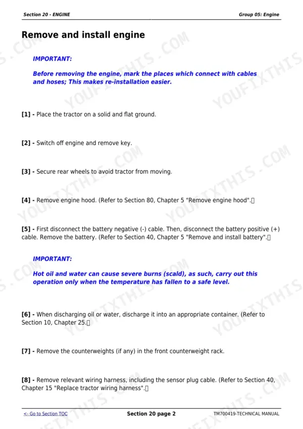
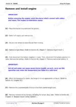
| Engine | 122-139 | Basic and Recommended Tools, Technical Specifications, Maintenance Intervals, Remove and Install Engine, Cylinder Head and Valve Service, Piston, Rod and Crankshaft Repair, Cooling System |
| Fuel System, Air Intake and Exhaust | 140-168 | Speed Control Lever (Technical Specifications, Check and Repair Engine Control Mechanism Assembly, Adjust Throttle Lever, Adjust Synchronization of Foot Throttle Pedal and Throttle Handle) |
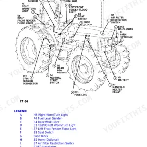
| Electrical System | 169-215 | Battery Removal and Installation, Starter Motor, Alternator and Charging Circuit, Wiring Harnesses and Connectors, Instrument Panel and Switches, Lighting, Fuses and Relays |
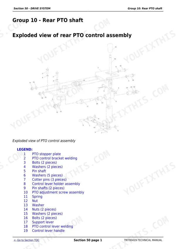
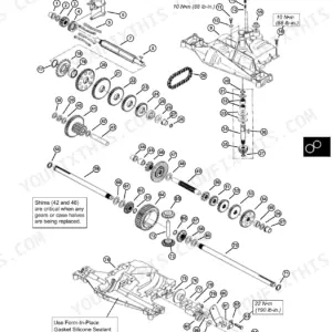
| Drive System | 216-395 | Rear PTO Shaft (Exploded View of Rear PTO Control Assembly, Exploded View of PTO Shaft Protection Cover Assembly, Exploded View of PTO Shaft, Remove, Check and Assemble PTO Control Assembly, Remove and Check Rear PTO Shaft Assembly, Assemble Rear PTO Shaft Assembly) |
| Steering and Brake | 396-478 | Steering System (Technical Specifications, Remove and Install Steering Wheel, Remove and Install Steering Column, Remove and Check Steering Gear Aggregate, Disassemble Hydraulic Steering Oil Tank, Remove, Check and Install Steering Cylinder Assembly, Disassemble Constant Flow Pump, Disassemble Full Hydraulic Steering Gear, Adjust Toe-In, Adjust Front Wheel Toe-In and Wheel Tread) |
| Hydraulic System | 479-503 | Hydraulic Pump and Lifter Filter Element (Remove Install: Gear Pump), Lifter (Technical Specifications, Remove and Install Lifter Assembly) |
| Miscellaneous | 504-548 | Engine Hood and Shield (Remove Engine Hood, Install Engine Hood, Remove and Install Engine Hood Strut, Remove and Install Engine Hood Lock, Remove and Install PTO Shaft Shield) |
| Driving Cab | 549-564 | Remove and Install Components (Remove Install: Fenders, Pedals, Rear-View Mirrors, Toolbox), Seat (Remove and Install Seat) |
| Special Tools (Made by Dealers) | 565-577 | Dealer-Fabricated Tools: Bearing and Bushing Installers (Q23-5, Q23-6), Pullers, Drivers and Gauges, Fabrication Drawings and Dimensions |
| Work Checking Procedures | 578-606 | Post-Repair Checks, Engine Operation Verification, Drive and Hydraulic Function Checks, Road and Field Test Procedures, Final Adjustment Sign-Off |
| Engine Operational Principles, Test and Adjust | 607-626 | Engine Component Locations, Theory of Operation, Compression and Oil-Pressure Tests, Valve Clearance and Injection Timing Adjustment, Engine Troubleshooting |
| Operation and Tests - Fuel/Air Intake Sys | 627-637 | Fuel System Component Locations, Injection Pump and Injector Operation, Fuel Delivery Tests, Air Intake and Exhaust Checks, Troubleshooting |
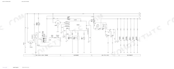
| Operation and Tests - Electrical System | 638-741 | Electrical Component Locations, Charging and Starting Circuit Operation, Wiring Schematics, Circuit Tests and Voltage Drops, Instrument and Lighting Diagnosis |
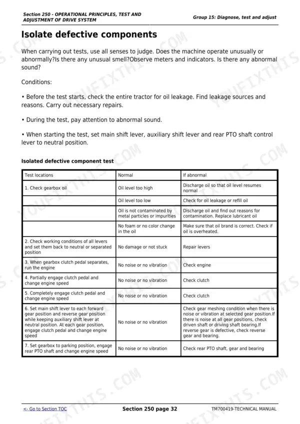
| Operation and Tests - Drive System | 742-789 | Drive System Component Locations, Clutch and Transmission Operation, PTO and Differential Operation, Clearance and Pressure Tests, Adjustment Procedures |
| Operation and Tests - Steering and Brakin | 790-825 | Steering Component Locations, Steering and Brake Operation, Free-Play and Pressure Tests, Brake Adjustment, Troubleshooting |
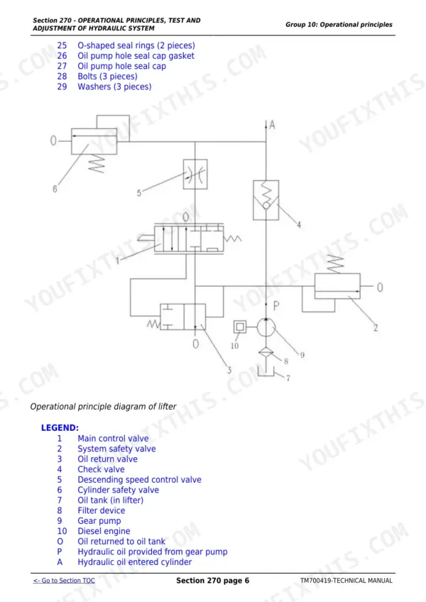
| Operation and Tests - Hydraulic System | 826-840 | Hydraulic Component Locations, Lifter Assembly Operation, Pump Pressure and Flow Tests, Lift Response Adjustment, Troubleshooting |
Quick Reference Specifications
| Specification | Value | Page |
|---|---|---|
| All Models | ||
| Prevent Battery Explosions | 4 | p. 6 |
| Handle Batteries Safely | 5 | p. 6 |
| Starter | QDJ1308L, 12V, 3kw | p. 59 |
| Fuel tank cap | properly installed | p. 89 |
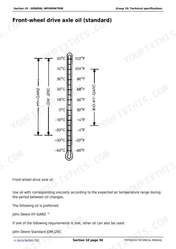
| Ambient temperature for engine oil of higher than normal viscosity | constantly above 30°C (86°F) | p. 90 |
| Radiator Capacity | 8 L (2.11 gal.) | p. 128 |
| Start motor (B) solenoid valve | Battery voltage | p. 677 |
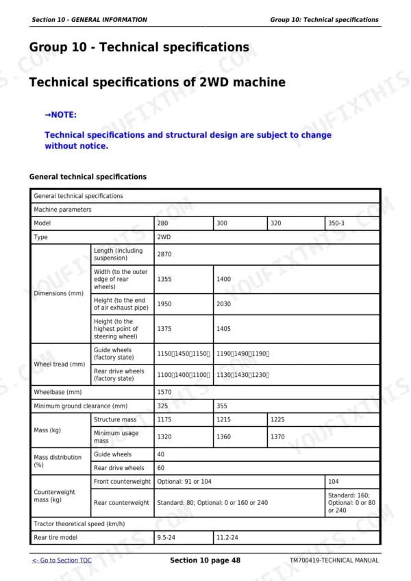
| Fuel tank capacity | 40 L | p. 73 |
| Engine oil capacity | 6~6.5 L | p. 73 |
| Gearbox oil capacity | 15~16 L | p. 73 |
| 280, 284, 300, 304 | ||
| Calibrated speed | 2200 r/min | p. 614 |
| 280, 284 | ||
| Maximum torque speed | 1500-1725 r/min | p. 614 |
John Deere 280-324 Series & B350 Common Problems This Manual Covers
John Deere 300 tractor won't start, starter clicks but engine cranks slowly or not at all
Test battery voltage at the positive terminal first; anything below 11.8 DC volts, charge or replace the 95D31L 12V 85Ah battery. Clean and tighten both ground cable connections at the frame. If the battery checks good, verify battery voltage reaches the starter solenoid terminal using the starting system tests on page 676.
Manual Section: Electrical System Diagnosis, Test and Adjustment p. 676Engine overheats under load, coolant boils over after an hour of heavy fieldwork
Check fan belt tension first: press at the middle of the belt with 29 to 39 N of force; deflection should measure 10 to 15 mm, per the check on page 621. Blow plugged radiator fins clear with compressed air, then verify the system holds its full 8 L (2.11 gal.) coolant charge.
Manual Section: Engine Diagnosis, Test and Adjustment p. 621Clutch slips under load, tractor loses forward drive when pulling implements uphill
Work through the clutch slippage procedure starting on page 773. Inspect the friction disc for glazing and oil contamination from a leaking rear main or input shaft seal, and adjust clutch pedal free play to spec. Check gearbox oil level too; overfilling past the 15 to 16 L capacity forces oil past seals.
Manual Section: Drive System Diagnosis, Test and Adjustment p. 773Three-point hitch lifts slowly or won't raise a loaded implement at full throttle
Check hydraulic oil level and condition first; the lifter circuit holds 7 to 8 L. Replace the lifter filter element if it has more than 500 operating hours on it, per page 482. Then run the slow-lift diagnosis starting on page 826, and torque any weeping M12x1.5 steel connectors to 21 N·m.
Manual Section: Hydraulic System Diagnosis, Test and Adjustment p. 826Engine runs rough and loses power, black exhaust smoke pours out under heavy load
Clean or replace the air filter element; it needs service every 50 hours, sooner in dusty conditions, per page 81. Inspect the fuel tank cap vent for clogging, drain stale fuel from the 40 L tank, refill with fresh diesel, then bleed air from the fuel system before restarting.
Manual Section: Fuel System, Air Intake and Exhaust p. 81Frequently Asked Questions
What are the torque specifications for the John Deere 284 engine bolts?
For the John Deere 284 tractor, the engine and clutch housing connecting bolt (M12 × 1.75) requires a tightening torque of 73 ~ 95 N·m (54 ~ 70 lb.-ft.). The engine and bracket connecting bolt (M16 x 2) requires a tightening torque of 144 ~ 160 N·m (106 ~ 118 lb.-ft.). p. 122
What is the engine oil capacity for the John Deere tractors?
The engine oil capacity for the John Deere tractors, using CD 15W-40 diesel engine oil (GB 11122-2006) for all four seasons, is 6 to 6.5 liters. p. 73
What is the fuel tank capacity for the John Deere tractors?
The fuel tank capacity for the John Deere tractors is 40 liters (10.56 gallons). It is recommended to fill the fuel tank at the end of each operating day to prevent condensation. p. 149
What is the radiator capacity for the John Deere tractors?
The radiator capacity for the John Deere tractors is 8 liters (2.11 gallons). p. 128
What is the maintenance interval for the lifter filter element?
Under normal working conditions, the maintenance interval for the lifter filter element is 500 operating hours. p. 482
What do I get after purchasing this John Deere 280 & variants manual?
Immediate download of the complete 840-page searchable Technical Manual. Access it on any device, from a laptop at your desk to a phone in the field.
Can I print pages of this manual for my own shop?
Yes. Print a chapter or just the pages for the job at hand, for use in your own shop. Any home or office printer works.









Reviews
There are no reviews yet.