
Part of the John Deere Repair Manuals.
All 312 pages of this John Deere Trail Buck Technical Manual (OEM #TM2160) focus on one machine family: the Trail Buck Utility ATV in 500, 650, 650EX, and 650EXT configurations. Inside, you get the Trail Buck Main Schematic for full electrical circuit tracing, a complete troubleshooting section covering cooling, magneto, lubrication, and cylinder diagnostics, plus page after page of torque tables spanning engine, CVT, drivetrain, brakes, and body fasteners. Exploded views walk you through every assembly from crankshaft and balancer to front differential backlash adjustment. Torque the cooling fan mount screw to 4.5 N·m (40 lb-in.) and confirm your headlights pull exactly 2 x 30 W before chasing an electrical fault with a multimeter and a prayer. Your machine is down. Get factory numbers, not forum guesses. Bookmarked by section and keyword-searchable; pull it up on your tablet, walk to the ATV, and start wrenching.
What's Inside This John Deere Trail Buck Series Manual
| System | Pages | Key Topics |
|---|---|---|
| Introduction | 3-4 | Table of Contents, Specifications and Information, Identification Numbers, Tools and Materials, Component Location, Schematics and Harnesses, Theory of Operation |
| Safety | 5-10 | Recognize Safety Information, Understand Signal Words, Replace Safety Signs, Handle Fluids Safely - Avoid Fires, Be Prepared for Emergencies |
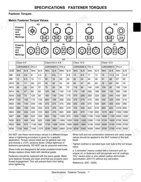
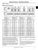
| Technical Data | 11-30 | Fastener Torques (Metric Fastener Torque Values, Inch Fastener Torque Values, Gasoline, Gasoline Storage, - Cycle Gasoline Engine Oil, Break-In Engine Oil - 4-Cycle Gasoline, Hydrostatic Transmission and Hydraulic Oil, Gear Case Oil, Gear Transmission Grease, Alternative Lubricants, Synthetic Lubricants, Lubricant Storage, Mixing of Lubricants, Oil Filters) |
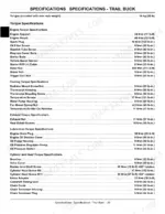
| Specifications | 31-35 | Engine Specifications - 500, Engine Specifications - 650, Engine Specifications - 500 and 650, Required Tools |
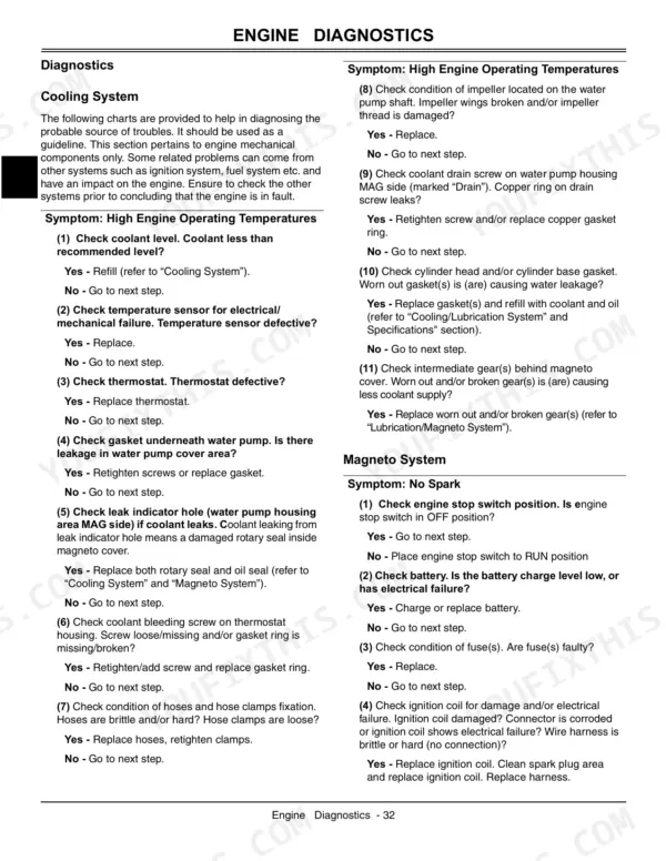
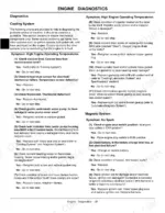
| Diagnostics | 36-47 | Cooling System, Magneto System, Lubrication, Cylinder and Head |
| Tests and Adjustments | 48-50 | Leak Test |
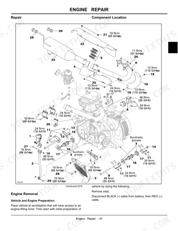
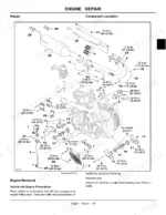
| Repair | 51-58 | Component Location, Engine Removal, Engine Installation, Anti-Vibration System |
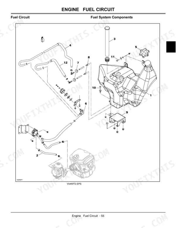
| Fuel Circuit | 59-64 | Fuel System Components, General, Fuel Lines, Fuel System Pressurization |
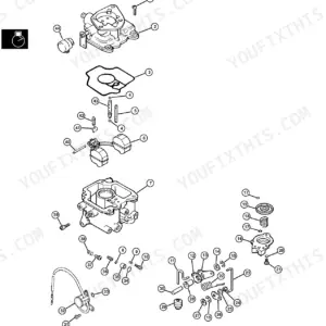
| Carburetor | 65-73 | Carburetor Components, Throttle Cable, Choke Cable |
| Fuel Circuit | 74-76 | Air Intake Components, Air Filter, Air Filter Cleaning/Draining, Air Filter Box |
| Cooling System | 77-88 | Engine Side Components, Vehicle Side Components, General, Coolant Level |
| Ignition and Charging System | 89-93 | Charging Components, General, Magneto Housing Cover, Seal |
| Oil System | 94-103 | Oil System Components, General, Engine Oil Pressure Test, Oil Change |
| Cylinder and Head | 104-194 | Cylinder Head Components, Piston and Rings Components, General, Spark Plug |
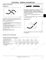
| Electrical | 195-236 | Specifications (Electrical Specifications, Required Tools, Recommended Tools), Schematics and Harnesses (Component Location, Trail Buck Main Schematic) |
| Drive Train | 237-260 | Required Tools (Special or Required Tools), Recommended Tools (Special or Required Tools), Repair, Front Drive Shaft (Removal, Inspection, Installation, Drive Shaft Boot Removal) |
| Steering | 261-268 | Specifications (Steering Control Specifications, Recommended Tools), Component Location (Steering System) |
| Suspension | 269-276 | Specifications (Suspension Specifications, Recommended Tools), Component Location (Swing Arm), Repair (General, Rear Shock, Swing Arm) |
| Brakes | 277-294 | Specifications (Brakes Specifications, Recommended Tools), Component Location (Front Brakes, Rear Brake) |
| Body / Frame | 295-312 | Repair, Body Parts (Trail Buck Series), Seat (Trail Buck Series), General, Steering Cover (Removal, Storage Cover), Console (Removal, Installation) |
Quick Reference Specifications
| Specification | Value | Page |
|---|---|---|
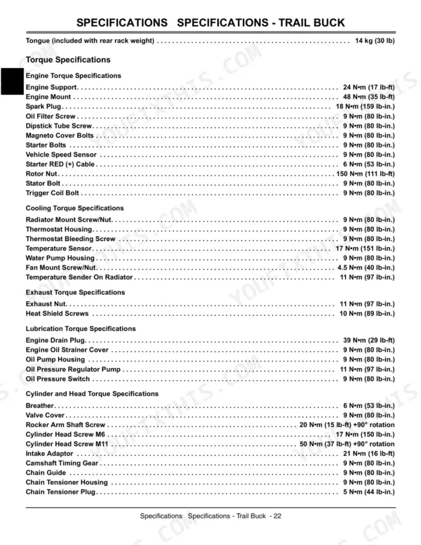
| Fan Mount Screw/Nut Torque | 4.5 N•m (40 lb-in.) | p. 26 |
| Pilot Lamp Cluster LED Voltage | 0.7 V approximately (each) | p. 198 |
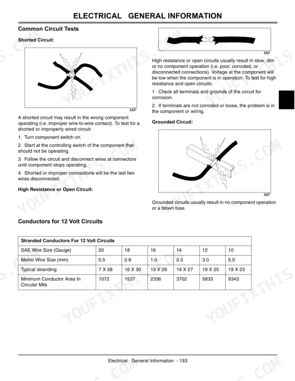
| SAE Wire Size (Gauge) | 20, 18, 16, 14, 12, 10 | p. 197 |
| Metric Wire Size (mm) | 0.5, 0.8, 1.0, 2.0, 3.0, 5.0 | p. 197 |
| Headlight Power Rating | 2 x 30 W | p. 198 |
| Fan Thermostat Switch ON Temperature | 95° C (203° F) | p. 23 |
| Fan Thermostat Switch OFF Temperature | 90° C (194° F) | p. 23 |
| Engine/Transmission Oil Capacity | 3 L (3.17 qt) | p. 25 |
| Fuel Tank Capacity | 21.8 L (5.8 U.S. gal) | p. 25 |
| Cooling System Capacity | 2.5 L (2.65 qt) | p. 25 |
| Spark Plug Torque | 18 N•m (159 lb-in.) | p. 26 |
| Engine Drain Plug Torque | 39 N•m (29 lb-ft) | p. 26 |
John Deere Trail Buck Series Common Problems This Manual Covers
Engine cranks but won't fire in any weather, confirmed no spark at plug
Inspect the spark plug; pull it, check the gap, and torque to 18 N•m (159 lb-in.) if reinstalling. If spark is absent, work through the ignition system test sequence starting at page 89. Verify the ignition switch delivers voltage to the coil before condemning the electronic module or stator.
Manual Section: Ignition and Charging System p. 89Multiple fuses blown, electrical system dead, four-wire harness connector burned or melted
Inspect the four-wire junction connector first; look for melted insulation, corrosion, and pushed-back terminals. Verify wire gauges match the schematic on page 197, where the harness runs sizes from 0.5 mm to 5.0 mm metric. Repair any damaged conductor before chasing individual fuses through the system.
Manual Section: Electrical p. 197Gauge cluster goes dark or flickers, intermittent power loss after water exposure
Remove the gauge cluster and inspect for water intrusion or burn marks. Test each pilot lamp LED: each should read approximately 0.7 V when powered, per the electrical specs on page 198. Disconnect the cluster first and recheck system voltage; a shorted cluster can pull down the entire harness.
Manual Section: Electrical p. 198Headlamps dim or dead, fuse keeps blowing on second or third start
Verify both headlamps are 30 W units (the circuit runs 2 x 30 W total, per page 198). Check for pinched wires or a loose connector at the harness junction. If the fuse blows repeatedly, trace the headlamp circuit through the wiring diagram on page 197 to isolate the short before replacing bulbs.
Manual Section: Electrical p. 197Frequently Asked Questions
What are the torque specs for the engine bolts on John Deere 650EX Trail Buck?
The manual provides various engine torque specifications for the John Deere 650EX Trail Buck. For example, the Engine Support bolts should be torqued to 24 N•m (17 lb-ft), Engine Mount to 48 N•m (35 lb-ft), and Spark Plug to 18 N•m (159 lb-in.). p. 26
What are the replacement specifications for Engine cooling fan?
The engine cooling fan is protected by a 15 A fuse. The fan thermostat switch should turn ON at 95°C (203°F) and OFF at 90°C (194°F). If the fan does not work after installing a jumper wire in the temperature sender connectors, it should be replaced. p. 19
What are the replacement specifications for Gauge cluster?
The Pilot Lamp Cluster uses LEDs, with each LED operating at approximately 0.7 V. If any LED in the speedometer burns out, the entire speedometer must be replaced as the LEDs are not available separately. p. 198
How do you fix john Deere Trail Buck cooling fan fails to engage, engine temperature climbs into the red?
Check coolant level first; top off to 2.5 L (2.65 qt) if low. Run the engine and verify the fan kicks on at 95°C (203°F). If it stays off, test the thermostat switch and fan motor per the cooling system diagnostics on page 77. When reinstalling, torque fan mount screws to 4.5 N•m (40 lb-in.). p. 77
What do I get after purchasing this John Deere 500 & variants manual?
Instant PDF download. You get the full 312-page searchable Technical Manual immediately after payment. Open it on your laptop, tablet, or phone right in the shop.
Is this John Deere 500 & variants Technical Manual printable?
Yes. Print a chapter or just the pages for the job at hand, for use in your own shop. Any home or office printer works.
Does this John Deere 500 & variants manual include wiring diagrams?
Yes. You'll find an electrical wiring diagram covering the main wiring layout.







Reviews
There are no reviews yet.