
![John Deere L100 L108 L110 L111 L118 L120 L130 Repair Manual [Lawn Garden Tractors]](https://youfixthis.com/wp-content/uploads/2018/03/Caterpillar-299D-299D-Compact-Track-2018-03-16_15-47-57-300x300.jpg)
Part of the John Deere Repair Manuals.
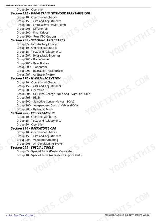
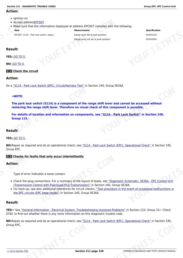
This is the complete John Deere factory Diagnosis and Tests service manual for nine 6030-series tractors: the 6130, 6230, 6330, 6430, 6530, 6534, 6630, 6830 and 6930. Across 3,661 pages it gives you every system test and diagnostic procedure a John Deere dealer technician uses to locate a fault without unnecessary teardown. The structure is deliberate: start with fault codes or observable symptoms, run the operational check, measure the test value, compare it to the printed specification, and then decide whether the component is at fault. That discipline covers the entire machine - from the CAN BUS and five ECU modules down through three transmission families, the full hydraulic circuit, fuel and cooling systems, electrical wiring, steering, brakes, and the operator cab.
Complete the set for your 6130, 6230, 6330…
- Repair Manual: John Deere 6830 & 6930 Premium Tractor Repair Manual
- Repair Manual: John Deere 6830, 6930 Tractor Repair Manual
What's Inside This John Deere 6130, 6230, 6330, 6430, 6530, 6534, 6630, 6830, 6930 Manual
| System | Pages | Key Topics |
|---|---|---|
| General Information | Safety Measures, General References, Torque Values, Electrical System Overview, Hydraulic System Overview | |
| Diagnostic Trouble Codes | Bcu Control Unit Codes, ECU Control Unit Codes, Epc Control Unit Codes, Prc Control Unit Codes, Tsc Control Unit Codes | |
| Observable Symptoms | Electronics Symptoms, Transmission Symptoms, Drive Train Symptoms, Steering and Brake Symptoms, Hydraulic System Symptoms, Cab Symptoms | |
| System Diagnosis | Electronics Diagnosis, PowrQuad Transmission Diagnosis, Hydraulic System Diagnosis | |
| Engine | General Information, Operational Checks, Tests and Adjustments | |
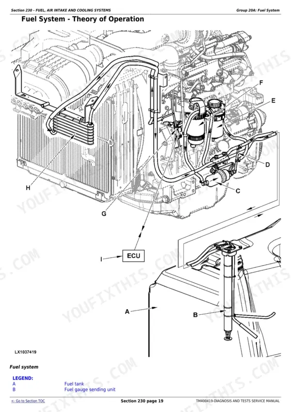
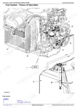
| Fuel, Air Intake and Cooling Systems | Fuel System Tests, Air Intake Checks, Cooling System Pressure Tests, Cold-Weather Starting Aids | |
| Electrical System | Starting Motor, Charging Circuit, Instrument Unit, Lights and Work Lights, Air Conditioning, Bcu Control Unit, CAN Bus System, Wiring Harnesses and Connectors, Ground Connections | |
| Electronic Control Units | Operation, Diagnostics, Interactive Tests, Calibrations, Reprogramming, Bcu, ECU, Epc, Prc, Tsc Control Units | |
| SyncroPlus Transmission | Synchronizer Operation, Shift-Fork Tests, Gear-Shift Adjustments, Clutch-Pack Inspection, Oil Pressure Checks | |
| PowrReverser Transmission | Forward-Reverse Clutch Tests, Reverser Solenoid Diagnostics, Clutch-Pack Pressure Checks, Shift-Quality Adjustment, Reverser Valve Inspection | |
| PowrQuad Transmission | Electrohydraulic Clutch Pack Tests, Clutch Calibration, Hydraulic Pressure Checks, Control Valve Diagnostics, Shift-Quality Adjustments | |
| Drive Train (Without Transmission) | Operational Checks, Tests and Adjustments, Front-Wheel Drive Clutch, Differential, Final Drives, Rear PTO Options | |
| Steering and Brakes | Introductory Checks, Hydrostatic Steering Tests, Brake Valve, Rear Brakes, Handbrake, Hydraulic Trailer Brake, Air-Brake System | |
| Hydraulic System | Operational Checks, Tests and Adjustments, Charge Pump, Hydraulic Pump, Hitch, Selective Control Valves, Independent Control Valves, Hydraulic Block | |
| Operator's Cab | Operational Checks, Tests and Adjustments, Ventilation, Heating, Air Conditioning System | |
| Special Tools | Dealer-Fabricated Tools, Available As Spare Parts |
Quick Reference Specifications
| Specification | Value | Page |
|---|---|---|
| 6130, 6230, 6330, 6430, 6530, 6534, 6630, 6830, 6930 | ||
| Engine ECU type | Level 16, 2-valve HPCR fuel system | |
| All models | ||
| Cooling system test pressure | 50 to 60 kPa (0.5 to 0.6 bar / 7 to 8.7 psi) | |
| Expansion tank cap - high-pressure valve opening | 70 to 90 kPa (0.7 to 0.9 bar / 10 to 13 psi) | |
| Thermostat nominal opening temperature | 82 degrees C (180 degrees F) | |
| Thermostat full-open temperature | 94 degrees C (202 degrees F) | |
| Fuel system pressure (before injection pump) | 60 kPa (0.6 bar / 8.7 psi) maximum | |
| Fuel transfer pump flow rate | 135 to 175 litres per hour (35.6 to 46.2 US gal/hr) | |
| Air intake low-pressure switch threshold | 5.9 to 6.9 kPa (59 to 69 mbar / 0.86 to 1 psi) | |
John Deere 6130, 6230, 6330, 6430, 6530, 6534, 6630, 6830, 6930 Common Problems This Manual Covers
Intermittent CAN BUS communication codes and erratic control-unit behavior across all systems
Inspect all chassis ground wire eyelets for breaks or corrosion, starting with the rear-chassis ground lug. The Electrical System section lists every ground connection point and provides the CAN BUS terminating resistor checks for both ends of the data bus. A single broken eyelet causes the control unit to drop off the bus intermittently, generating codes in multiple modules and making the fault look like a controller failure when it is simply a bad ground.
Manual Section: Electrical SystemComplete or severe loss of hydraulic function - loader sluggish, hitch will not lift, pump noise on engagement
Begin with the charge pump output test in the Hydraulic System section before condemning the main pump. Low charge pressure accelerates pump wear and mimics pump failure. Check hydraulic oil level and condition, replace the filter on its service interval, and run the pump flow test at rated RPM. If charge pressure is within spec and main pump flow is low, the pump or its coupling are the next items to inspect.
Manual Section: Hydraulic SystemPTO does not engage or disengage, or slips under load
Test the PTO solenoid voltage and ground circuit first using the procedure in the Electrical System section, then move to the Drive Train section for the PTO clutch pack pressure check. A failed solenoid will not build pack pressure even with good mechanical components. If pressure is present but the PTO still slips, inspect the circlip in the PTO pack - a dislodged circlip allows the pack to spin without fully locking and destroys the clutch discs under load.
Manual Section: Drive Train (without Transmission)Engine cranks but will not start, or starts hard in cold weather despite glow plugs operating
Verify the fuel system supply pressure against the 60 kPa maximum listed in the Fuel, Air Intake and Cooling Systems section. Air in the fuel system after a filter change or a weak transfer pump are the most common causes of hard starting once the battery and starter circuit check out. The Engine section covers operational checks and the cold-weather starting aid circuit, including the electrical starting-aid heater element voltage test, so you can confirm the aid is actually energizing before the crank cycle.
Manual Section: EngineFrequently Asked Questions
How do I read and clear fault codes on a John Deere 6930 or 6630 tractor?
The Diagnostic Trouble Codes section covers every code generated by the BCU, ECU, EPC, PRC and TSC control units, with the fault description and required action listed for each. The Electronic Control Units section then walks through the interactive test and diagnostic menu access so you can read active codes, review stored codes and clear them after the underlying fault is corrected.
What causes intermittent communication errors and erratic behavior on John Deere 6-series tractors?
A broken eyelet on a chassis ground wire is the most common cause of intermittent CAN BUS communication losses. The Electrical System section covers all ground connection locations and the CAN BUS terminating resistor checks so you can pin down the open ground or failing termination resistor before replacing an expensive control unit.
How do I test hydraulic system pressure on a John Deere 6530 or 6830 tractor?
The Hydraulic System section provides step-by-step tests for the charge pump, main hydraulic pump output, hitch circuit, and selective and independent control valves. Each test lists the test port location, the gauge fitting required, and the specification to compare your reading against, so you can confirm whether a slow loader or failing hitch is caused by a worn pump, internal leakage or a faulty valve.
Why does the PTO fail to engage on a John Deere 6430 or 6930?
PTO engagement failures are commonly traced to the PTO solenoid or a damaged circlip in the PTO pack. The Drive Train section covers operational checks and adjustment procedures for all rear PTO configurations so you can test the solenoid energization, check clutch pack engagement pressure, and identify whether the fault is electrical or mechanical before pulling the drivetrain.
What is the correct cooling system test pressure for John Deere 6230 and 6330 tractors?
The cooling system should be pressure-tested at 50 to 60 kPa (0.5 to 0.6 bar / 7 to 8.7 psi). The expansion tank cap high-pressure valve opens at 70 to 90 kPa (10 to 13 psi). The Fuel, Air Intake and Cooling Systems section covers the full pressure-test procedure and thermostat check so you can confirm a cooling complaint before draining the system.
Is this John Deere 6130 manual a download or a disc?
You get a 3661-page searchable PDF (108 MB) that downloads instantly after checkout. Open it on your laptop, tablet, or phone, and bring it right to the shop floor.
Can I print specific sections of this John Deere 6130 Diagnostic?
Yes. Print a chapter or just the pages for the job at hand, for use in your own shop. Any home or office printer works.









Reviews
There are no reviews yet.