
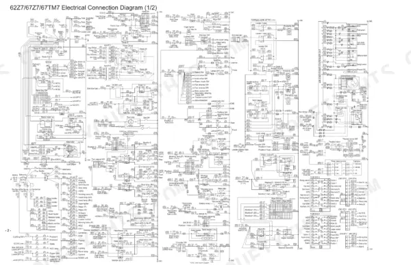
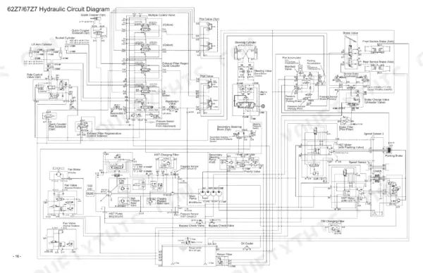
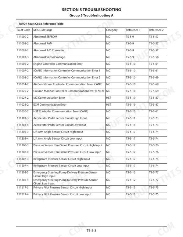
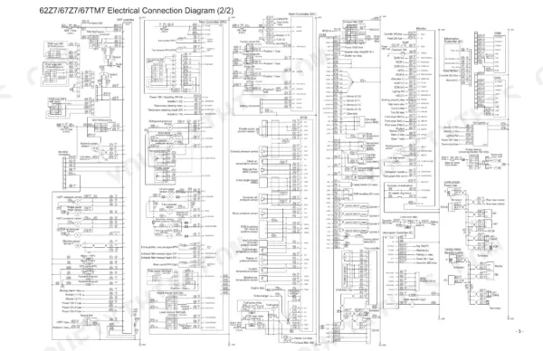
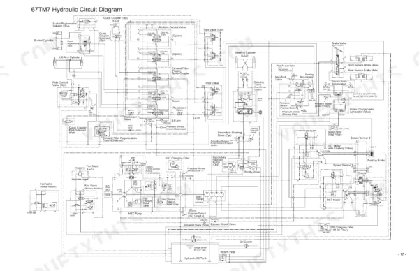
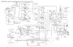
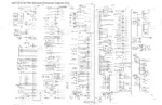
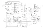
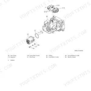
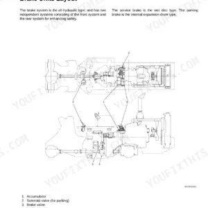
When an HST wheel loader loses drive under load or the boom ignores the joystick, a hunch about the cause can burn a full shift. The Kawasaki 62Z7, 67Z7, 67TM7 shop manual PDF (OEM ID 93207-01021) is the 987-page factory book for all three machines. Hydraulic circuit diagrams trace oil from the HST pump through the multiple control valve, priority valve and steering valve, while the wiring diagrams map each controller and ECM harness on the loader. System theory fills roughly a quarter of the book, and troubleshooting tables with fault code listings tie each symptom to the circuit behind it. Check your suction strainer against its 177 μm filtration rating, and torque the pump shuttle valve to 50 N·m (37 lbf·ft) on reassembly. Alone with a dead loader, you have nobody to ask. Bookmarked and text-searchable, the PDF rides on your laptop or phone to wherever the machine sits.
What's Inside This Kawasaki 62Z7, 67Z7, 67TM7 Manual
| System | Pages | Key Topics |
|---|---|---|
| Introduction | 4-5 | To the Reader, Safety Alert Symbol |
| Symbol and Abbreviation | 6-7 | Transmission, Main Controller, Engine Control Module, Hydrostatic Transmission Controller, Diesel Particulate Filter, Exhaust Gas Recirculation |
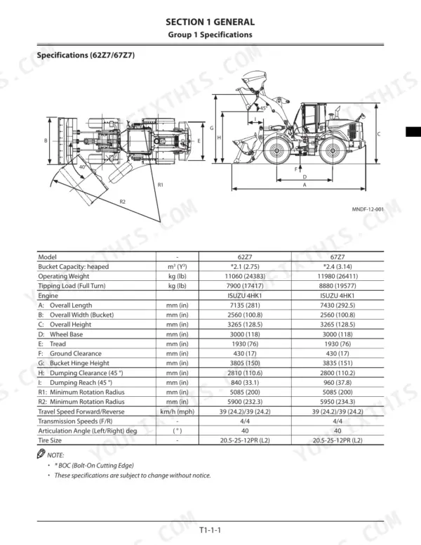
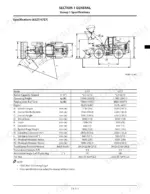
| General | 8-47 | Specifications, Component Layout, Component Specifications |
| System | 48-287 | Controller, Control System, ECM System, Hydraulic System, Electrical System |
| Pump Device | 288-313 | HST Pump Layout, Rotary Group, Displacement Angle Control Cylinder, Cutoff Valve, 4-Gear Pump Unit |
| HST Motor | 314-327 | HST Motor Layout, Rotary Group, Regulator, Motor Displacement Angle Control, Flushing Valve |
| Multiple Control Valve | 328-355 | Multiple Control Valve Hydraulic Diagram, Main Relief Valve, Overload Relief Valve, Flow Rate Control Valve, Pilot Operation Control Circuit |
| Fan Motor and Fan Valve | 356-369 | Fan Motor, Fan Valve, Fan Speed Control, Fan Reverse Rotation Control, Make-Up Operation |
| Steering Valve | 370-379 | Steering Valve Structure, Steering Operation, Overload Relief Valve, Make-Up Valve |
| Priority Valve | 380-389 | Priority Valve Structure, Priority Valve Operation, Steering Stop Circuit |
| Pilot Valve | 390-419 | Joystick Type Pilot Valve, Fingertip Control Type Pilot Valve, Auxiliary Pilot Valve, Electromagnetic Detent |
| Brake Charge Valve, Manifold Valve, Transmission, Axle, and Others | 420-504 | Brake Charge Valve, Manifold Valve, Transmission Clutch Operation, Differential Principle, Propeller Shaft, HST Cooler Bypass Check Valve |
| Operational Performance Test | 505-602 | Engine Test, Machine Performance Test, Component Test, Adjustment |
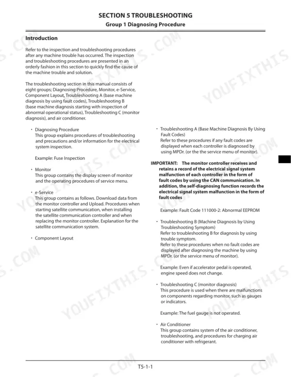
| Troubleshooting | 603-672 | Diagnosing Procedure, Monitor, e-Service, Component Layout |
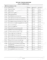
| Troubleshooting a | 673-778 | Fault Codes, MPDr. Fault Code Reference Table, HST Controller Fault Code List |
| Troubleshooting B | 779-888 | Troubleshooting Symptom |
| Troubleshooting C | 889-922 | Monitor Diagnosis |
| Air Conditioner | 923-970 | Air Vent Damper Servo Motor |
| Diagrams | 971-987 | Electrical Connection Diagram, Wiring Diagrams, Hydraulic Circuit Diagram |
Quick Reference Specifications
| Specification | Value | Page |
|---|---|---|
| Shuttle valve tightening torque | 50 N·m (5 kgf/m, 37 lbf·ft) | p. 309 |
| Nut type pipe with dia. 8 tightening torque | 11.8 to 14.7 N·m (8.7 to 10.8 lbf·ft) | p. 966 |
| Battery Voltage | 12 V | p. 39 |
| Battery Capacity | 64 Ah | p. 39 |
| Suction Filter Filtration | 177 μm | p. 44 |
| Pilot Filter, Charge Oil Filter Filtration | 1.4 or more (filters 30% or more particles 10 μm in diameter) | p. 44 |
| Engine Rated Output | 115 kW/2200 min-1 (156 PS/2200 rpm) | p. 34 |
| Cooling Fan Diameter | 650 mm (25.6 in) | p. 35 |
| HST Pump Maximum Flow Rate | 0 to 242.9 L/min-1 at 2200 min-1 | p. 40 |
| Service Brake Accumulator Capacity | 1.4 L (1.48 quart) | p. 41 |
| Steering Valve Overload Relief Set-Pressure | 24.6 MPa (251 kgf/cm2, 3568 psi) | p. 42 |
| Transmission Clutch Pressure | 1.8 to 2.0 MPa (18 to 20 kgf/cm2, 261 to 290 psi) | p. 42 |
Kawasaki 62Z7, 67Z7, 67TM7 Common Problems This Manual Covers
Kawasaki 62Z7 front attachment lift arms and bucket lacking power or drifting with load raised
Check main relief valve set pressure against 20.6 MPa (2988 PSI) using the procedure on page 553 before you condemn a pump. If pressure holds but the arms still creep, inspect the overload relief valves in the multiple control valve section starting on page 328. Trace the circuit on the hydraulic schematic, page 986.
Manual Section: Multiple Control Valve p. 328Loader steering operation feels weak or slow, and secondary steering does not respond
Check steering valve overload relief set-pressure against 24.6 MPa (3568 psi), listed on page 42. Inspect the steering valve overload relief and make-up valves following page 370, then verify priority valve operation on page 380 and the steering stop circuit on page 179. Trace the steering lines on the hydraulic schematic, page 986.
Manual Section: Steering Valve p. 370Service brakes weak with stopping distance running long on the brake function check
Test service brake performance with the function check on page 531; stopping distance should be 14 m (45 feet) or less. If it runs long, inspect the brake charge valve following page 420 and verify the service brake accumulator, rated at 1.4 L (1.48 quart) on page 41, is charging and holding.
Manual Section: Brake Charge Valve, Manifold Valve, Transmission, Axle, and Others p. 531Loader slow to shift speeds or hesitating when changing between forward and reverse travel
Measure transmission clutch pressure against the 1.8 to 2.1 MPa (261 to 305 PSI) standard following page 574. If readings are low, work through the transmission clutch operation coverage in the section starting on page 420. If pressure is in range, read the HST controller codes in the error code reference before pulling anything apart.
Manual Section: Travel System TroubleshootingMonitor panel displaying an MC, HST or ECM controller fault code during operation
Read the active code through the monitor service menu, then match it to the error code reference. Before replacing a controller, inspect connectors and wire harnesses following the diagnosing procedure, and trace the affected circuit on the wiring diagram starting on page 972.
Manual Section: Troubleshooting A (Fault Codes)Frequently Asked Questions
How do I reset error codes on a Kawasaki 62Z7 wheel loader?
To reset fault codes, you must first correct the machine trouble. Once corrected, the fault code displayed by the service menu of the monitor will be deleted automatically. In cases where problems are not easily predictable, you can check the fault code using MPDr. Note that the 'RETRIAL' procedure is required to erase accumulated fault codes from the controller memory to confirm if any fault codes are indicated after the retrial. p. 609
What are the replacement specifications for the Kawasaki 62Z7 fuel filters and water separator?
The manual specifies that the fuel system uses a Fuel Main Filter and a Fuel Pre-Filter, with a Water Separator available as an option. Specific replacement intervals are not listed in this manual. p. 25
What is the standard valve clearance for the ISUZU 4HK1 engine on the Kawasaki 62Z7, 67Z7, 67TM7 wheel loader?
The standard valve clearance for both the inlet and exhaust valves on the ISUZU 4HK1 engine is 0.4 mm (0.016 in) when the engine is cool. p. 36
What is the standard charging pressure for the Kawasaki 62Z7 service brake accumulator?
The standard charging pressure for the service brake accumulator is 6.8 MPa (69 kgf/cm², 986 psi) at 20 °C (68 °F). p. 41
What is the procedure for bleeding air from the Kawasaki 62Z7 brake system?
To bleed the brake system, set the parking brake switch to ON, start the engine, and attach a clear vinyl tube to the air bleed plug, inserting the other end into a container filled with hydraulic oil. Depress the brake pedal several times and hold it at the stroke end, then loosen the air bleed plug for several seconds. Repeat this until bubbling stops, then keep bleeding until about 0.5 L (0.5 quart) of hydraulic oil is drawn from each of the 4 wheel locations after bubbling stops. p. 881
Will this Kawasaki 62Z7 Shop Manual download right away?
Straight to your device: 987 pages of searchable Shop Manual, downloadable the moment payment goes through.
Is this Kawasaki 62Z7 manual print-friendly?
Yes. Many buyers print one chapter at a time for their own shop and keep the rest on a tablet.


Reviews
There are no reviews yet.