
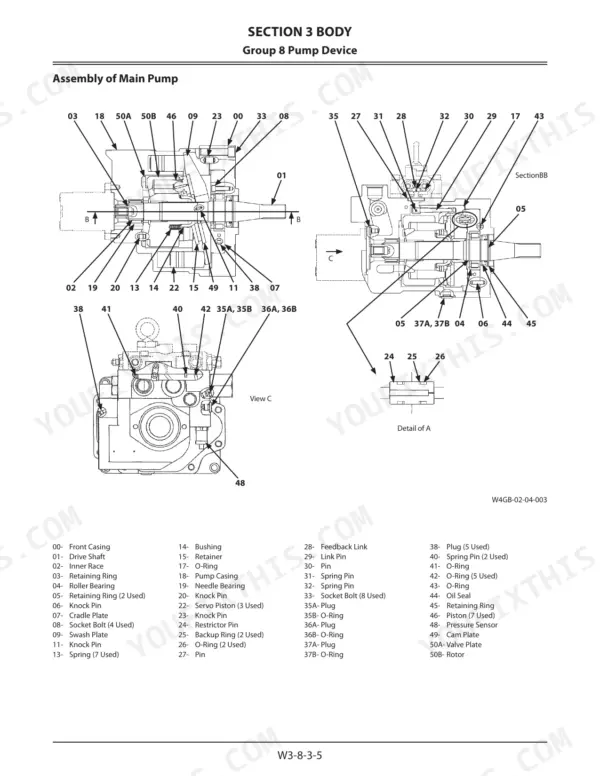
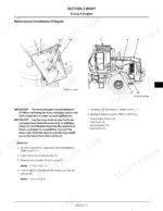
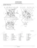
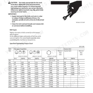
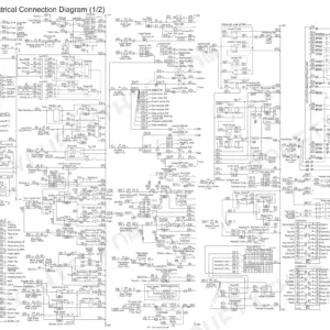
The Kawasaki 80Z7 shop manual PDF (OEM ID 93209-00600) takes your machine apart and puts it back together across 740 pages, from cab and counterweight removal to the last steering cylinder seal. The travel system alone claims roughly a third of the book: tires, drive unit, axles, propeller shaft, brake valve, steering pilot valve, steering valve and the secondary steering device. Exploded views back up the pump device and control valve teardown, while the priority valve, brake charge valve, ride control accumulator and center hinge each get their own procedures, and a maintenance standard section sets wear limits for the body and front attachment. Hold a remanufactured lift arm cylinder rod to 85 mm (-0.012/-0.027 mm), and refill the engine with 25 L (6.6 US gal) of oil. Every hour the machine sits parked is an hour of material not moving. A searchable text layer puts you on the right valve section in seconds.
What's Inside This Kawasaki 80Z7 Manual
| System | Pages | Key Topics |
|---|---|---|
| General Information | 1-40 | Tightening, Painting, Bleeding Air, Pressure Release Procedure, Preparation |
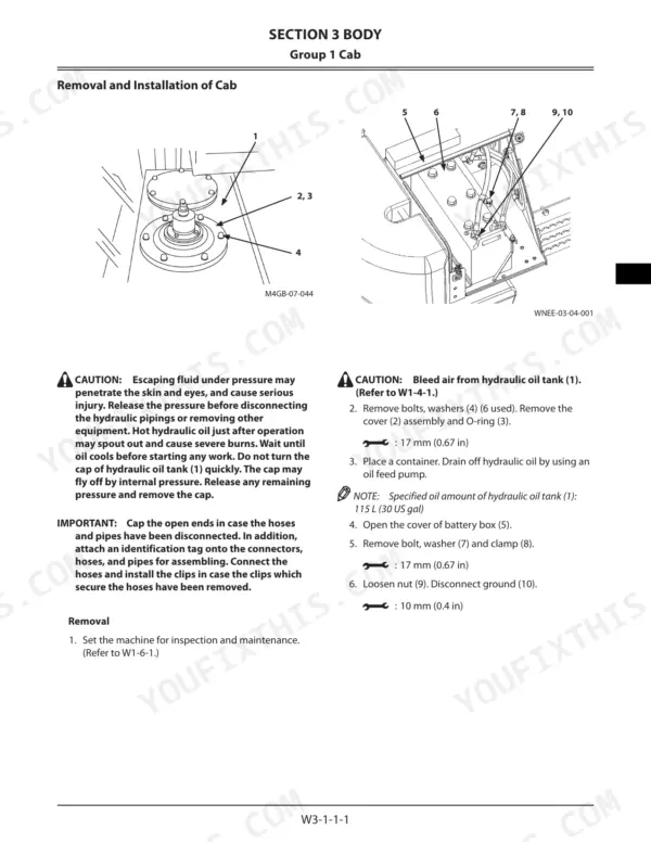
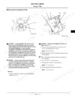
| Cab, Counterweight, and Center Hinge | 53-116 | Cab Removal, Counterweight Installation, Center Hinge Maintenance, Hydraulic Hose Routing |
| Engine and Radiator Assembly | 117-186 | Engine Removal, Exterior Parts Installation, Radiator Replacement, Cooling Fan System |
| Hydraulic Oil Tank and Fuel Tank | 187-210 | Hydraulic Oil Tank Removal, Fuel Tank Maintenance, Fuel System Bleeding, Tank Installation |
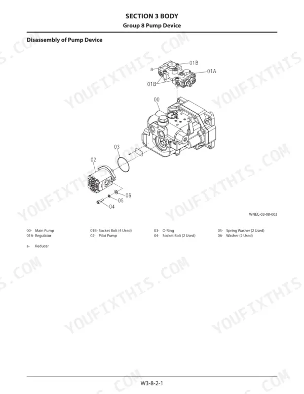
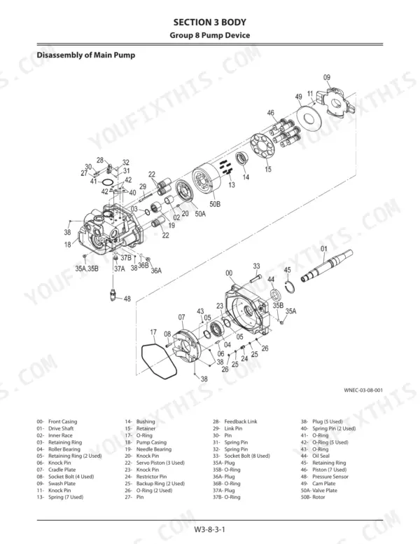
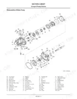
| Pump Device and Control Valve | 211-282 | Pump Device Disassembly, Control Valve Assembly, Priority Valve, Pilot Valve |
| Pilot Valve and Brake Charge Valve | 283-332 | Pilot Valve Removal, Brake Charge Valve Structure, Brake Accumulator Maintenance, Brake System Bleeding |
| Manifold Valve, Solenoid Valve, and Flow Regulator | 333-372 | Manifold Valve Removal, Solenoid Valve Unit, Flow Regulator Valve, Brake Solenoid Valve |
| Cooling Fan System and Exhaust Filter | 373-424 | Fan Valve Removal, Fan Motor Maintenance, Exhaust Filter Assembly, Exhaust Filter Regeneration |
| Travel System | 425-674 | Tire, Drive Unit, Axle, Propeller Shaft, Brake Valve, Steering Pilot Valve, Steering Valve, Steering Cylinder |
| Front Attachment | 675-740 | Cylinder |
Quick Reference Specifications
| Specification | Value | Page |
|---|---|---|
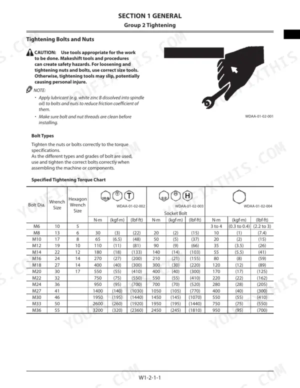
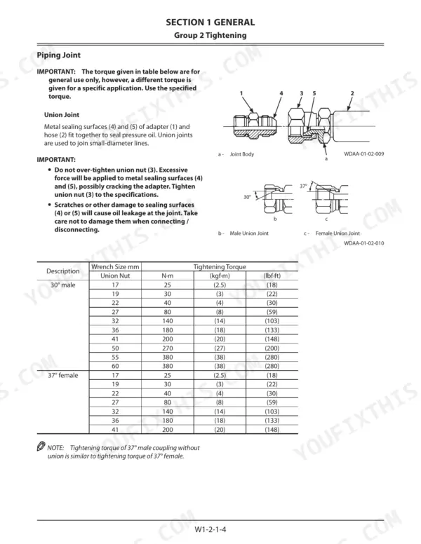
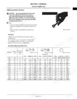
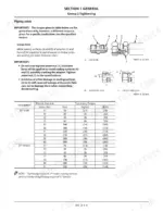
| Union Nut Tightening Torque (30° male, 17 mm wrench) | 25 N·m (18 lbf·ft) | p. 14 |
| Union Nut Tightening Torque (37° female, 17 mm wrench) | 25 N·m (18 lbf·ft) | p. 14 |
| Lift Arm Cylinder Rod Recommended Size After Remanufacturing | 85 mm (upper -0.012 mm, lower -0.027 mm) | p. 49 |
| Bucket Cylinder Rod Recommended Size After Remanufacturing | 95 mm (upper -0.012 mm, lower -0.027 mm) | p. 49 |
| Amount of engine oil | 25 L (6.6 US gal) | p. 118 |
| Amount of transmission oil | 40 L (10.6 US gal) | p. 118 |
| Tightening torque for pipe (8) bolts and washers (7) | 50 N·m | p. 163 |
| Tightening torque for air cleaner (1) assembly bolts and washers (4) | 90 N·m | p. 163 |
| Pump control valve (20C) removal tool size | 27 mm (1.06 in) | p. 266 |
| Overload relief valves (06D) removal tool size | 41 mm (1.61 in) | p. 266 |
| Transmission filter head socket bolt torque | 34 N·m (3.4 kgf·m, 25 lbf·ft) | p. 448 |
| M6 Bolt Torque (unmarked head) | 3 to 4 N·m (0.3 to 0.4 kgf·m, 2.2 to 3 lbf·ft) | p. 11 |
Kawasaki 80Z7 Common Problems This Manual Covers
Kawasaki 80Z7 hydraulic oil tank and pump circuit holding trapped air after an oil change or pump service
Bleed air from the hydraulic oil tank following page 25, then torque the tank cap socket bolts to 20 N·m (14.8 lb·ft). Check the oil level against the 115 L tank capacity listed on page 55. Page 26 covers bleeding the hydraulic system: fill the pump first, start at slow idle and stroke the cylinders slowly before full travel.
Manual Section: Bleeding Air from Hydraulic Oil Tank p. 25Lift arm or bucket cylinder rod bent or showing runout during cylinder overhaul inspection
Measure cylinder rod bend and run out against the limits on page 49. Repair the rod at 0.5 mm (0.02 in) bend or 1.0 mm (0.04 in) run out. Replace it at 1.0 mm (0.04 in) bend or 2.0 mm (0.08 in) run out. When remanufacturing, hold the lift arm rod to 85 mm and the bucket rod to 95 mm, minus 0.012 to 0.027 mm.
Manual Section: Front Attachment p. 49Hydraulic hose union nut or O-ring seal joint fitting loose after hose or component reinstallation
On page 14, 30° male and 37° female union nuts with a 17 mm wrench size take 25 N·m (18 lbf·ft); larger nuts take higher values from the same table. Page 15 lists O-ring seal joints at 30 N·m (22 lbf·ft) for a 19 mm wrench size. Recheck every fitting you broke before the machine goes back to work.
Manual Section: General Information p. 14Ride control accumulator still holding pressure before front attachment hydraulic lines are opened
Release ride control accumulator pressure following the procedure on page 32 before you crack any line, and release front attachment circuit pressure as well. On reassembly, torque plug (5) to 7 N·m (5.2 lbf·ft) and lock nut (6) to 10 N·m (7.4 lbf·ft). Never loosen a fitting on a charged accumulator.
Manual Section: Ride Control Accumulator Pressure Release p. 32Steering cylinder head, rod nut or set screw loose after a steering cylinder overhaul
Torque the steering cylinder head and rod nut to 491±49 N·m and the set screw to 15±1.5 N·m following page 660. Before reassembly, check the rod against the 45 mm remanufacturing size on page 49, and replace any rod with a bend of 1.0 mm (0.04 in) or more.
Manual Section: Travel System p. 660Transmission filter head loose or leaking at the seal after a filter change service
Fasten the transmission filter head with its two socket bolts at 34 N·m (25 lbf·ft) following page 448, then turn the filter itself 3/4 turn after the seal touches. Check the transmission oil level and inspect the filter seat for leaks before you put the machine back to work.
Manual Section: Travel System p. 448Frequently Asked Questions
What is the specified tightening torque for an M16 bolt on the Kawasaki 80Z7?
Page 11 lists an M16 bolt at 270 N·m (27 kgf·m, 200 lbf·ft) for 10.9/T-marked bolts, 210 N·m (21 kgf·m, 155 lbf·ft) for socket bolts, and 80 N·m (8 kgf·m, 59 lbf·ft) for bolts with an unmarked head. A torque given for a specific job overrides this general table. p. 11
What is the specified oil capacity for the hydraulic oil tank on the Kawasaki 80Z7?
The specified oil capacity for the hydraulic oil tank is 115 L (45 US gal). p. 211
What is the procedure for bleeding air from the fuel system?
To bleed air from the fuel system, loosen the air bleed plug (1) and operate the feed pump (2) until no air bubbles are observed. Once no air bubbles are present, tighten the plug and continue operating the feed pump until it becomes difficult to move. p. 27
What is the weight of the bucket cylinder for the Kawasaki 80Z7?
The weight of the bucket cylinder is 170 kg (375 lb). p. 680
What is the standard backlash specification for the ring gear on the Kawasaki 80Z7?
The standard backlash for the ring gear (33) is 0.25 to 0.38 mm (0.010 to 0.015 in). p. 576
Is this Kawasaki 80Z7 manual a download or a disc?
You get a 740-page searchable PDF that downloads instantly after checkout. Open it on your laptop, tablet, or phone, and bring it right to the shop floor.
Am I able to print pages from this Kawasaki 80Z7 manual?
Yes. Print the pages or sections you need for your own shop use. Any standard printer works.


Reviews
There are no reviews yet.