
Built for the Kawasaki 70Z7 and 70TM7 wheel loaders, this 912-page Kawasaki 70Z7, 70TM7 shop manual PDF (OEM part number 93208-00772) is the factory disassembly and assembly book for both machines. The travel system takes up roughly a quarter of the book: tire, drive unit, axle, propeller shaft, brake valve and steering device work. The pump device, control valve and pilot valves each get full removal and teardown procedures. Center hinge, brake charge valve, accumulator, fan motor and quick coupler solenoid valve get the same treatment, and maintenance standards give you service limits for the body, travel system and front attachment. Refill the hydraulic tank to its 140 L (37 US gal) total, and run the transmission drain plug back in at 80 N·m (59 lbf·ft). You don't drop a loader axle on guesswork. Bookmarked and searchable, the PDF prints cleanly, so the drive unit pages can go to the bench and soak up grease.
What's Inside This Kawasaki 70Z7, 70TM7 Manual
| System | Pages | Key Topics |
|---|---|---|
| General Information | 1-51 | Precautions for Disassembling and Assembling, Tightening, Painting, Bleeding Air, Releasing Pressure, Preparation |
| Maintenance Standard | 52-71 | Body Maintenance Standard, Travel System Maintenance Standard, Front Attachment Maintenance Standard |
| Cab and Counterweight | 72-131 | Cab Removal and Installation, Counterweight Removal and Installation, Battery Box Removal and Installation, Battery Disconnect Switch |
| Center Hinge and Engine | 132-209 | Center Hinge Removal and Installation, Engine Removal and Installation, Exterior Parts Removal and Installation, Air Cleaner Removal and Installation |
| Radiator and Hydraulic Oil Tank | 210-263 | Radiator Assembly Replacement, Hydraulic Oil Tank Removal and Installation, Fuel Tank Removal and Installation, Exterior Parts Removal |
| Pump Device and Control Valve | 264-341 | Pump Device Removal and Disassembly, Control Valve Removal and Disassembly, Pilot Valve Removal and Disassembly, Auxiliary Pilot Valve |
| Brake Charge Valve and Accumulator | 342-421 | Brake Charge Valve Removal and Structure, Brake Accumulator Removal and Installation, Pilot Valve Disassembly and Assembly |
| Solenoid Valve and Cooling Fan System | 422-526 | Parking Brake Solenoid Valve, Quick Coupler Solenoid Valve, Cooling Fan System Removal and Installation, Fan Motor and Fan Pump Disassembly |
| Travel System | 527-754 | Tire, Drive Unit, Axle, Propeller Shaft, Brake Valve, Steering Device |
| Front Attachment | 755-912 | Front Attachment Removal and Installation, Cylinder |
Quick Reference Specifications
| Specification | Value | Page |
|---|---|---|
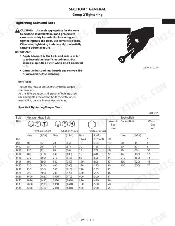
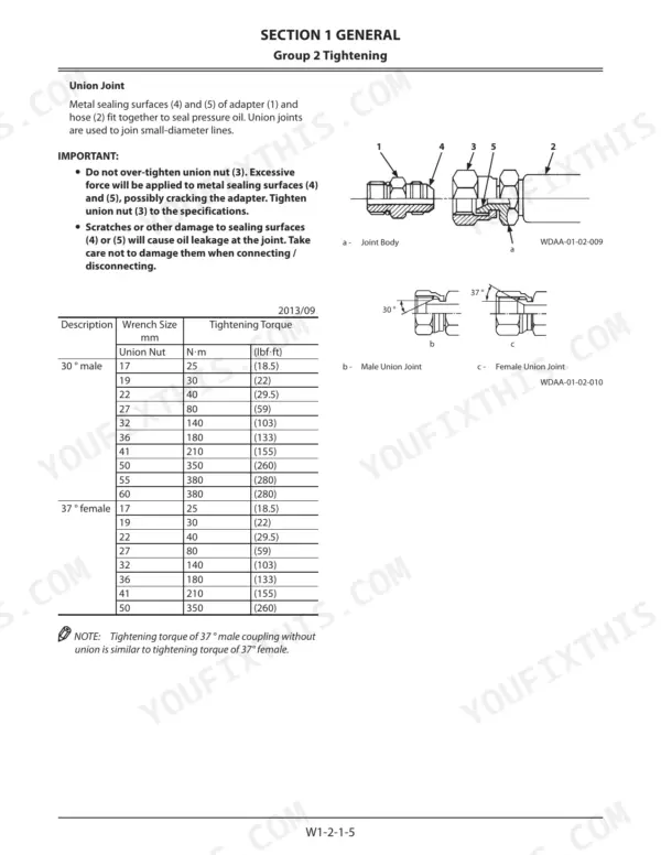
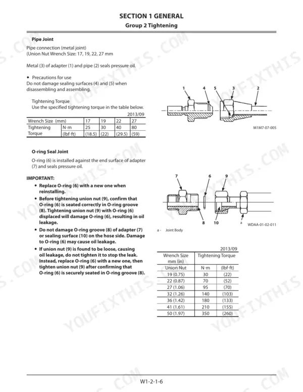
| Union Nut Tightening Torque (30° male, 17mm) | 25 N·m (18.5 lbf·ft) | p. 16 |
| Union Nut Tightening Torque (30° male, 19mm) | 30 N·m (22 lbf·ft) | p. 16 |
| Hydraulic oil tank cap socket bolt torque | 9 N·m (0.9 kgf·m, 6.6 lbf·ft) | p. 38 |
| Total oil amount of hydraulic oil tank | 140 L (37 US gal) | p. 180 |
| Transmission oil drain plug torque | 80 N·m (8 kgf·m, 59 lbf·ft) | p. 182 |
| Amount of transmission oil | 30 L (7.9 US gal) | p. 182 |
| Engine oil drain plug torque | 93 N·m (9.3 kgf·m, 69 lbf·ft) | p. 182 |
| Amount of engine oil | 25 L (6.6 US gal) | p. 182 |
| Fuel filter (3) assembly mounting bolt torque | 17 mm | p. 189 |
| Fuel tank total oil amount | 235 L (62.1 US gal) | p. 256 |
| T-Bolt Type Band Clamp Tightening Torque | 4.5 N·m | p. 19 |
| Worm Gear Type Band Clamp Tightening Torque | 6 to 7 N·m | p. 19 |
Kawasaki 70Z7, 70TM7 Common Problems This Manual Covers
70Z7 and 70TM7 union nut or O-ring seal joint weeping oil at the fitting
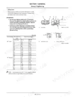
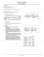
Release pressure from the front attachment hydraulic circuit and ride control accumulator before cracking any line. Do not just tighten a weeping O-ring seal joint: the manual says to replace the O-ring with a new one, confirm it is seated in its groove, then tighten the union nut. Union nut torque per page 16: 40 N·m (29.5 lbf·ft) on a 22mm, 80 N·m (59 lbf·ft) on a 27mm. O-ring seal joints use different values on page 17; a 22mm takes 70 N·m.
Manual Section: Tightening Bolts and Nuts p. 16Hydraulic oil tank refilled after service and air still trapped in the hydraulic system
Bleed air from the hydraulic oil tank and then the hydraulic system, following the Bleeding Air procedure that starts on page 38. Torque the tank cap socket bolts to 9 N·m (6.6 lbf·ft) when you close it up. Page 74 lists the hydraulic oil tank total oil amount as 140 L (37 US gal).
Manual Section: Bleeding Air p. 38Center hinge pin and bushing worn at the articulation joint, with play beyond maintenance standard
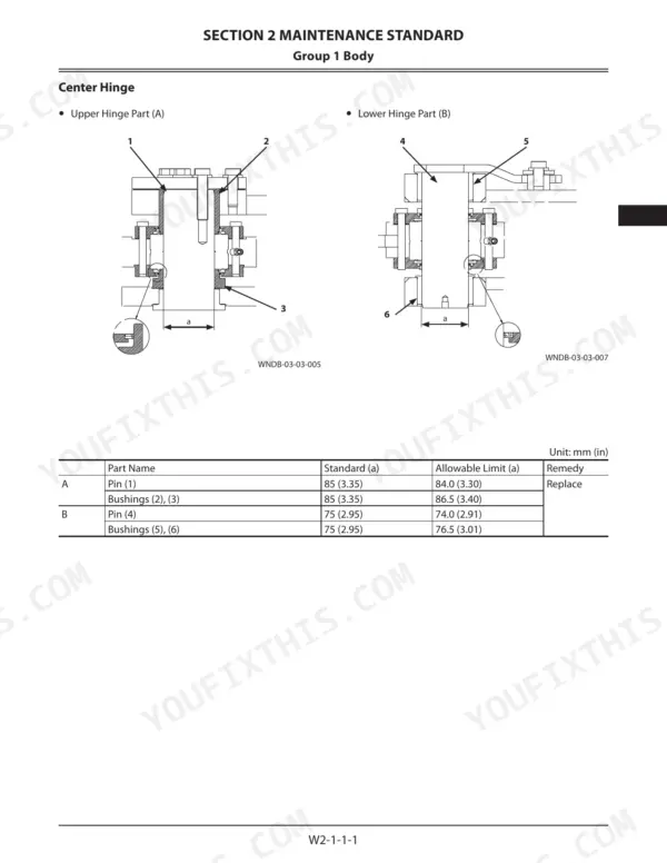
Park the loader, lock the chassis and support the lift arms before you touch the center hinge. Measure the center hinge pin and bushing and compare them to the Maintenance Standard (Body) dimensions on page 54. Replace worn parts using the Center Hinge Removal and Installation procedure.
Manual Section: Maintenance Standard (Body) p. 54Lift arm and bucket pins and bushings worn, or front attachment cylinder rod bent with run out
Release pressure in the front attachment hydraulic circuit and support the lift arms before pulling pins. Measure pin and bushing dimensions and check each cylinder rod for bend and run out against the Front Attachment Maintenance Standard starting on page 60. Repair or replace anything out of standard, as the table remedy column specifies, using the Front Attachment Removal and Installation procedure.
Manual Section: Maintenance Standard (Front Attachment) p. 60Transmission oil level low or drain plug seeping after a transmission oil change
Clean the transmission drain plug seat, then torque the plug to 80 N·m (59 lbf·ft) following page 182. Refill with the 30 L (7.9 US gal) of transmission oil specified on that same page. Check the plug again for seepage once the oil is warm and the machine has cycled.
Manual Section: Center Hinge and Engine p. 18220.5R25 radial tire air pressure dropping below standard between shifts on a loaded machine
Check each 20.5R25 tire and set it to the 400 kPa standard air pressure listed on page 532. Adjust within the 400 to 500 kPa radial tire range on page 533 to suit the job. When a tire has to come off, plan the lift for 360 kg per tire.
Manual Section: Travel System p. 532Frequently Asked Questions
What are the wheel-bolt torque specifications for a Kawasaki 70Z7/70TM7?
The wheel bolt torque specification for the Kawasaki 70Z7/70TM7 is 890 N·m (91 kgf·m, 660 lbf·ft). This applies to both the front and rear tires. p. 532
What is the total oil capacity of the hydraulic oil tank for the Kawasaki 70Z7/70TM7?
The total oil capacity of the hydraulic oil tank for the Kawasaki 70Z7/70TM7 is 140 liters (37 US gallons). p. 74
What is the procedure for bleeding air from the hydraulic oil tank?
To bleed air from the hydraulic oil tank, park the machine on a level surface, stop the engine, and push the air bleed button on the tank. Then, remove the socket bolts and cap, and install a vacuum pump to maintain negative pressure in the tank while working. p. 38
What is the torque specification for the main relief valve on the control valve on the Kawasaki 70Z7/70TM7?
The main relief valve on the control valve should be tightened to 180 to 210 N·m (18 to 21 kgf·m, 133 to 155 lbf·ft). p. 309
What is the standard backlash for the ring gear on the Kawasaki 70Z7/70TM7?
The standard backlash for the ring gear is 0.25 to 0.38 mm (0.01 to 0.015 in). p. 677
What format is this Kawasaki 70Z7 manual in?
Immediate download of the complete 912-page searchable Shop Manual. Access it on any device, from a laptop at your desk to a phone in the field.
Is printing allowed for this Kawasaki 70Z7 Shop Manual?
You can. Print the sections you want for your own use and keep the file as your backup.


Reviews
There are no reviews yet.