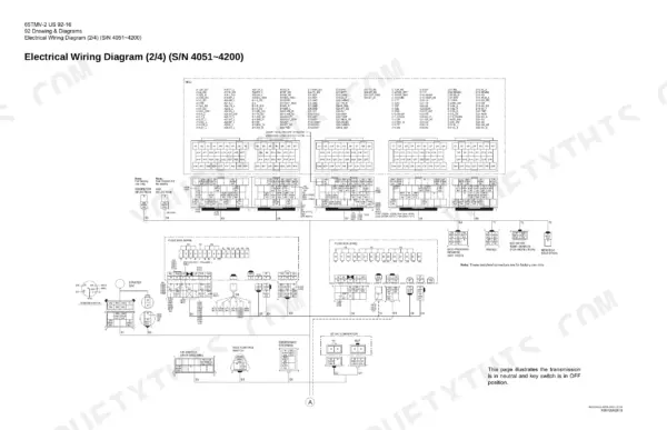
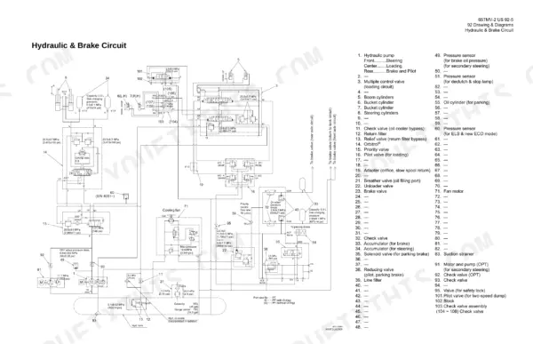
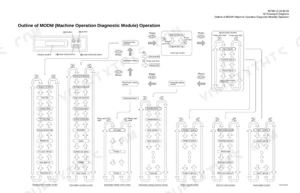
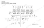
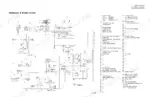
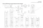
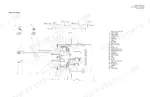
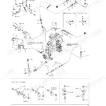
Kawasaki 65TMV-2 wheel loaders from serial 4001 onward are covered by this 68-page Kawasaki 65TMV-2 service manual PDF, with the electrical work split at each serial break: 4001 to 4030, 4031 to 4050, 4051 to 4200, and 4201 up. Wiring diagrams take up most of the book, with a full set per serial group, plus MCU connector layouts, an abbreviation chart, cab circuits, and connection diagrams for the engine ECM and air conditioning. The hydraulic and brake schematics trace oil from the pump through the multiple control valve to the boom, bucket and steering cylinders, then through the unloader valve, brake valve and accumulator; the MODM diagnostic section ends with an input/output signal table. Plan on 95 L when you refill the hydraulic tank. Chase a fault on the wrong serial's print and you end up buying the wrong relay. Bookmarks by serial group and a searchable text layer take you straight to your machine's sheet.
What's Inside This Manual
| System | Pages | Key Topics |
|---|
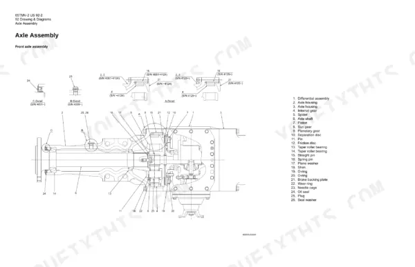
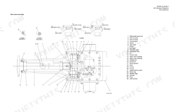
| Axle Assembly | 2-3 | Front Axle Assembly, Rear Axle Assembly |
| Torque Converter and Transmission | 4 | Pump Impeller, Turbine Impeller, Stator |
| Hydraulic & Brake Circuit | 5 | Hydraulic Pump, Multiple Control Valve, Boom Cylinders |
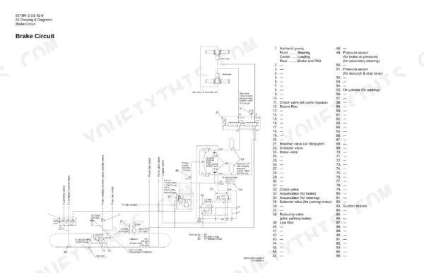
| Brake Circuit | 6 | Hydraulic Pump, Return Filter, Breather Valve |
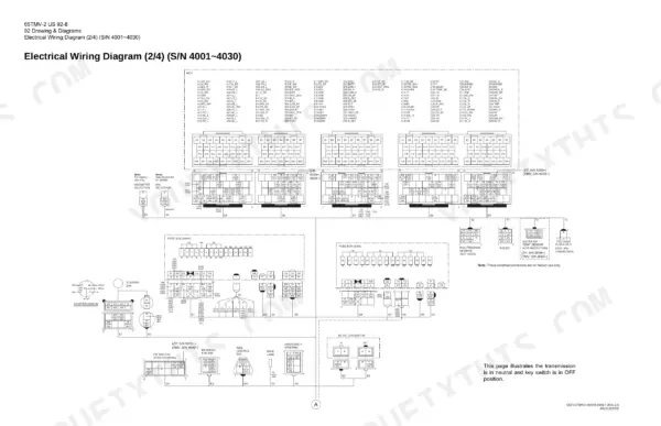
| Electrical Wiring Diagrams (S/N 4001-4030) | 7-10 | Wiring Diagram 1/4, Wiring Diagram 2/4, Wiring Diagram 3/4, Wiring Diagram 4/4 |
| Electrical Wiring Diagrams (S/N 4031-4050) | 11-14 | S/N 4031~4050 |
| Electrical Wiring Diagrams (S/N 4051-4200) | 15-18 | S/N 4051~4200 |
| Electrical Wiring Diagrams (S/N 4201~) | 19-22 | S/N 4201~ |
| Electrical Wiring Diagram Connectors and Abbreviations | 23-26 | MCU Connector Layout, Abbreviation Chart, Connector Identification |
| Electrical Wiring Diagram (CAB) | 27-29 | CAB Wiring, Radio, Wiper Motor, Cigar Socket |
| Electrical Connection Diagrams | 30-37 | Connection Diagram 1/2, Connection Diagram 2/2, E/G ECM Connection, Air Conditioning Connection |
| Cabin Air Conditioner Electrical | 38-41 | Cabin Air Conditioner Connection, Equipment Operation Table |
| Electrical Equipment Layout | 42-58 | Front Chassis, Rear Chassis, Floor Board |
| MODM Operation | 59-68 | Input/Output Monitor |
Quick Reference Specifications
| Specification | Value | Page |
|---|
| Hydraulic tank capacity | 95 L | p. 5 |
| Power supply voltage | +24 V | p. 25 |
| Controller sensor output voltage | +5 V | p. 25 |