Kobelco K909-II, K909LC-II Shop Manual with Wiring Diagrams

$49.99 USD · one-time payment

Model: K909-II | K909LC-II
Type: Hydraulic Excavator
Serial: K909-II LL-1201~ | K909LC-II LQ-1601~
531 Pages·37 MB·Searchable PDF·English·Print-Ready
  • ✓ Wiring Diagrams
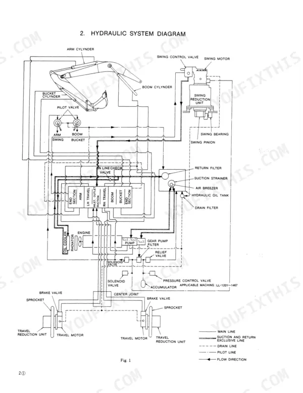
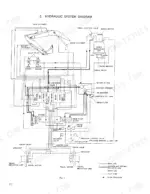
  • ✓ Hydraulic Schematics
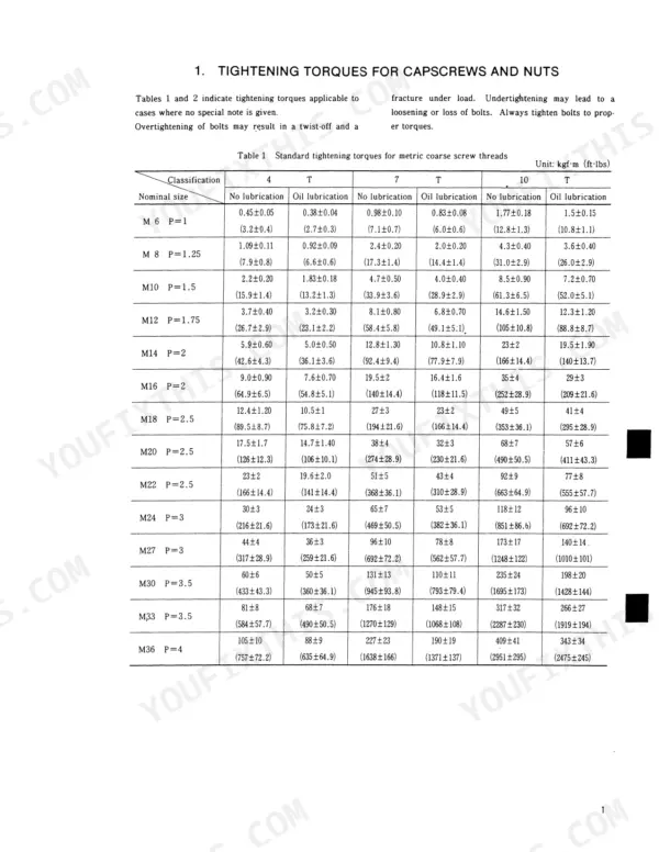
  • ✓ Torque Specs
  • ✓ Multi-Level Bookmarks (2-level navigation)
Preview Sample Pages (PDF)
Add to Cart
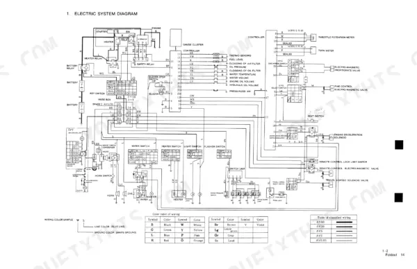
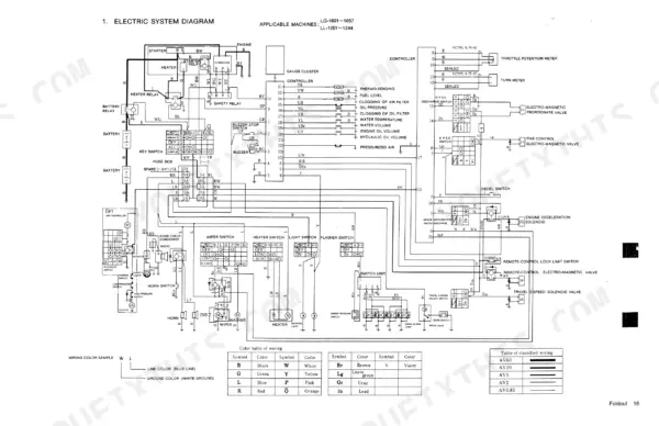
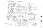
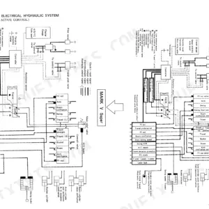
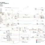
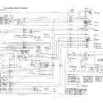
Kobelco K909-II, K909LC-II electric system wiring diagram showing battery, controller, switches, and color code table.
Kobelco K909-II, K909LC-II Shop Manual with Wiring Diagrams
$49.99

Instant Download 24/7

  • Works on PC, Mac, tablet, and phone.
  • Download once, keep forever


Guaranteed Safe Checkout
Visa Mastercard PayPal Apple Pay Google Pay

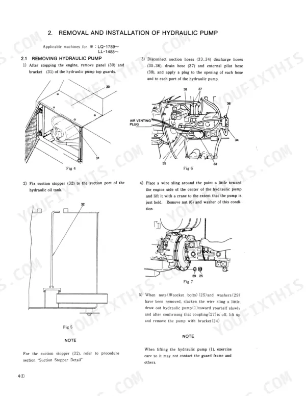
The Kobelco K909-II, K909LC-II shop manual PDF (OEM ID S5LQ0003E-02) takes both hydraulic excavators apart across 531 pages, from the travel reduction unit and swivel joint through the hydraulic pump, control valve and every cylinder. Hydraulic schematics trace oil from the pump through the control valve to the swing and travel motors, and wiring diagrams map the electrical system down to the cluster gauge and Intelligent Total Control System. Component overhaul fills more than half the book; troubleshooting sorts faults by drive, hydraulic, swing, travel and attachment system so you can pin a weak travel motor before a hose comes off. Expect each 23 x 17.6 x 2 mm shim to move the low pressure relief setting about 6 kgf/cm² (85 psi), and torque 22 x 3.0 mm tube fittings to 22 ± 2 kgf-m (158 ft-lbs). An excavator parked for want of one number costs your crew a day. Bookmarked, text-searchable, and yours to keep for this machine.

What's Inside This Manual

SystemPagesKey Topics
Operation and Controls4-5How to Index Each Shop Manual Section, List of Shop Manual
Specification6-21Names of Components, General Dimensions, Specifications and Performance
Location and Weight of Components22-27Location of Components, Weight of Components, Transportation Weight
Maintenance Standards and Test Procedures28-59Pressure Measurement and Adjustment, Cylinder Speed, Cylinder Oil-Tightness, Swing Performance, Travel Performance
Troubleshooting60-83Drive System, Hydraulic System, Swing System, Travel System, Attachment System
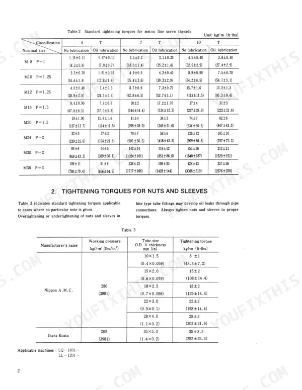
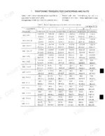
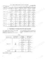
Working Standards84-87Tightening Torques for Capscrews, Nuts, And Sleeves
Systems - Drive, Hydraulic, Swing, Travel, Attachment, Control, Upper Frame, Air, Electrical88-172Drive System, Hydraulic System, Swing System, Travel System, Attachment System, Control System, Upper Frame, Air System
Attachments173-192Attachment System, Backhoe Attachments, Removing/Installing Bucket and Arm, Maintenance Standards for Attachments
Control System193-206Engine Control System, Travel Control System, Hydraulic Control System, Solenoid Valve, Pressure Control Valve
Upper Frame207-220Fuel Tank, Counterweight, Cab, Upper Frame Disassembly/Mounting
Air System221-224Air System Operation, Compressor, Safety Valves, Air Reservoir
Electrical System225-238Electrical System Diagram, Cluster Gauge Lamp, Intelligent Total Control System
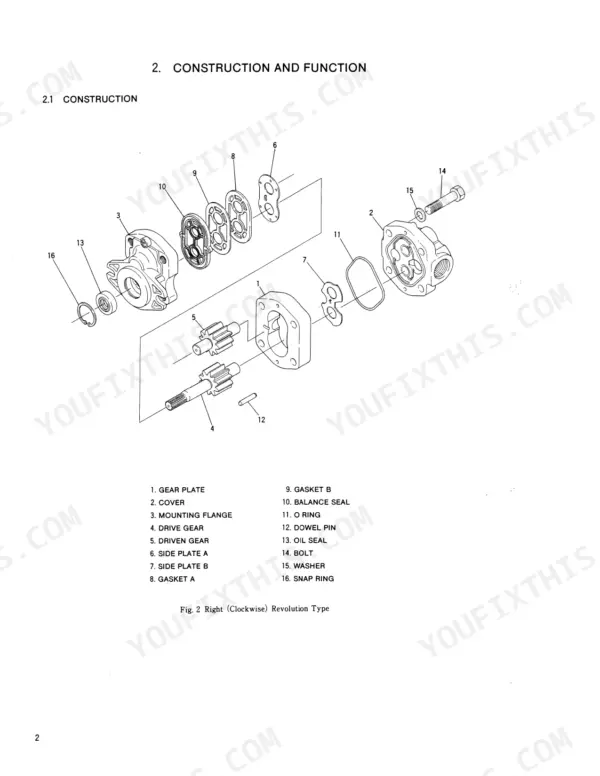
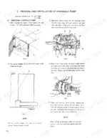
Components - Reduction Unit, Hydraulic Pump, Control Valve, Hydraulic Motor, Swivel Joint, Hydraulic Cylinder239-252Reduction Unit, Hydraulic Pump, Control Valve, Hydraulic Motor, Swivel Joint, Hydraulic Cylinder, Hydraulic Gear Pump
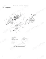
Hydraulic Pump and Regulator253-330Hydraulic Pump, Replacement Standards of Abrasive Parts, PQ Curve of Pump, Regulator
Hydraulic Motor (Swing) and Pilot Valve331-356Hydraulic Motor, Fault Finding of Motor Proper, Pilot Valve
Control Valve, Swing Control Valve and Travel Brake Valve357-436Control Valve, Pressure Adjustment for Relief Valves, Swing Control Valve, Brake Valve (Travel)
Hydraulic Motor (Swing) and Travel Motor437-470Hydraulic Motor, Hydraulic Motor (Travel), Parts Maintenance Standards
Swivel Joint471-482Usable Limit of the Parts, Inspection Procedure and Remedy
Hydraulic Cylinder483-502Preparation Before Disassembly, Inspection After Disassembly
Reduction Unit (Swing and Travel)503-531Reduction Unit, Shim Adjusting Procedure, Functional Principle

Quick Reference Specifications

SpecificationValuePage
Low pressure relief valve pressure adjustmentabout 6 kgf/cm² (85 lbs/in²) per 23x17.6x2mm shimp. 36
Tightening Torque for Plug (152)0.85-1.15 kgf-m (6.1-8.3 ft-lbs)p. 395
Tightening torque for 10x1.5 mm tube size6 ± 1 kgf-m (43.3 ± 7.2 ft-lbs)p. 87
Tightening torque for 15x2.0 mm tube size15 ± 2 kgf-m (108 ± 14.4 ft-lbs)p. 87
Tightening torque of socketscrew (A)33 ± 3.0 kgf·m (238.1 ± 21 ft-lbs)p. 100
Tightening torque of socketscrew (C)44 ± 0.4 kgf·m (317.5 ± 3 ft-lbs)p. 100
Socket bolts fastening swing motor and swing reduction unit (LQ-1601~1788, LL-1201~1487)28.5 ± 3 kgf·m (205 ± 21.6 ft-lbs)p. 141
Socket bolts fastening swing motor and swing reduction unit (LQ-1789~, LL-1488~)18.5 ± 2 kgf·m (133 ± 14.4 ft-lbs)p. 141
Socket bolts fastening swing reduction unit and upper frame55 ± 6 kgf·m (396 ± 43.3 ft-lbs)p. 141
Valve plate and shoe plate hardnessHS78 min.p. 466
Gap between piston and caulked part of shoe0-0.1 mmp. 467
Boom Cylinder Weight220 kg (485 lbs)p. 485
BrandKobelco
ModelK909-II, K909LC-II
Machine TypeHydraulic Excavator
Manual TypeShop Manual
LanguageEnglish
FormatSearchable PDF (Digital Download)
Pages531
File Size37 MB
Manual No.S5LQ0003E-02
Serial RangeK909-II LL-1201~, K909LC-II LQ-1601~
Wiring DiagramsYes
Hydraulic SchematicsYes
Torque SpecificationsYes
Bookmarked / IndexedYes