| Difference of Major Function | 6 | Front a/C Duct, Swing Flasher, Safety Bumper, 12v Power Source, Loading Mode, Travel Preferential |
| Interchangeability List | 7-10 | E/G Oil Filter, Hyd Tank Breather, Air Element, Radiator Assy, Swing Motor Assy, Cab |
| Name of Components | 11 | Bucket Cylinder, Arm Cylinder, Boom Cylinder, Swing Motor, Control Valve |
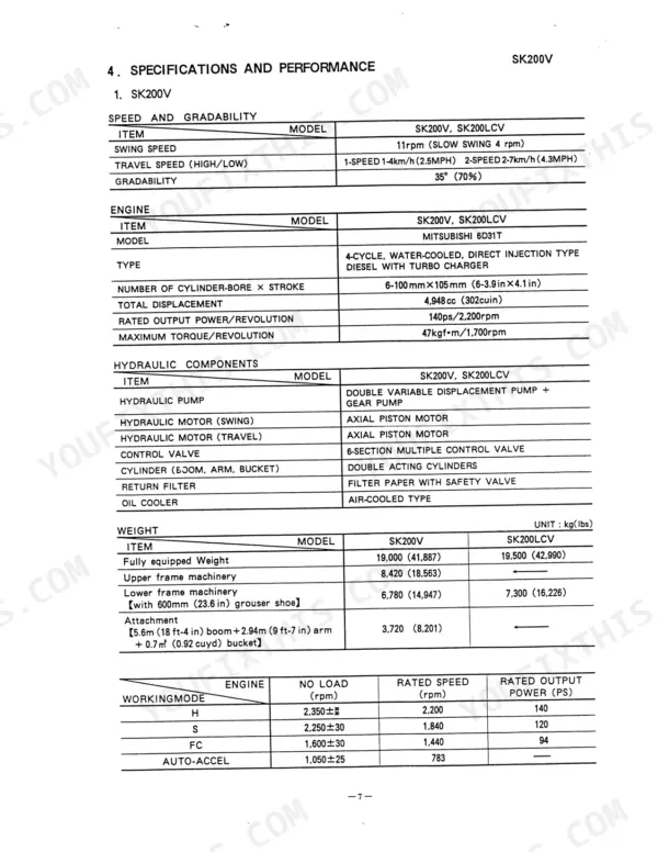
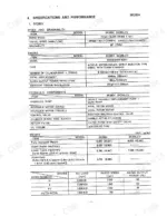
| Specifications and Performance | 12-14 | Swing Speed, Travel Speed, Engine Model, Hydraulic Pump, Weight, Working Mode |
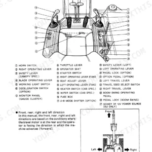
| Layout Operating Controls | 15-36 | Air Conditioner Operating Panel, Remote Control Safety Lever Lock, Left Operating Lever, Throttle Lever, Starter Switch, Operator Seat |
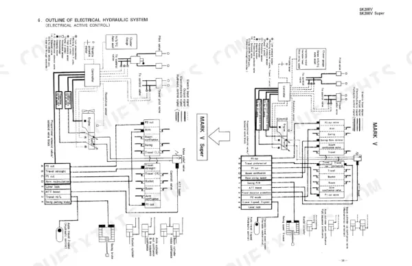
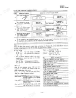
| Outline of Electrical Hydraulic System | 37-38 | Cluster Gauge, Proportional Solenoid Valve, Revolution Sensor, Throttle Potentiometer, Hydraulic Pump, Control Valve |
| Locations of Mechatronics | 39 | Mechatro-Controller, Low Pressure Sensor, High Pressure Sensor, Proportional Solenoid Valve Block |
| Hydraulic Pump | 40-52 | Regulator, Solenoid Valve, Gear Pump, Suction Port, Delivery Port, Gauge Port |
| Main Control Valve | 53-61 | Main Relief Valve, Port Relief Valve, Lock Valve Operation, Boom Up Confluence, Arm Out Confluence, Bucket Dump |
| Swing Motor | 62-68 | Specification, Construction, Swing Brake, Reverse Protection Valve, Port Relief Valve |
| Travel Motor | 69-76 | Appearance, Specification, Structure, Pilot Selector Valve, Over-Load Relief Valve, Brake Valve, Counterbalance Valve |
| Hydraulic Cylinder | 77-78 | Construction, Cushion Mechanism, Rod Side Cushion, Bottom Side Cushion |
| Pilot Valve | 79-80 | Outside View, Specifications, Structure, Hydraulic Diagram |
| Solenoid Valve | 81-86 | Location, Structure, Proportional Solenoid Valve, Swing P/B Solenoid Valve |
| Pressure Sensor | 87 | High Pressure Sensor, Low Pressure Sensor, Structure |
| Swivel Joint | 88-89 | Major Specifications, Structure, Seal Assembly |
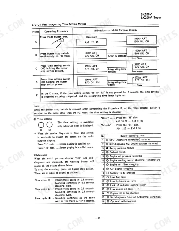
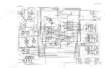
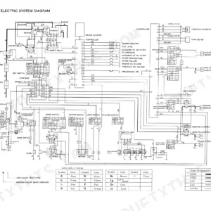
| Locations Electric Components | 90-94 | Switch, Sensor, Solenoid, Relay, Light, Controller, Motor, Electric Fittings |
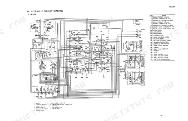
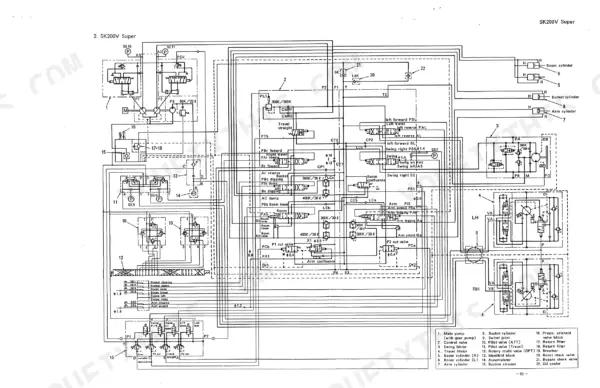
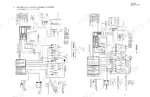
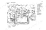
| Hydraulic Circuit Diagram | 95-96 | Main Pump, Control Valve, Swing Motor, Travel Motor, Hydraulic Cylinder, Pilot Valve, Solenoid Valve, Pressure Sensor |
| Components Function List | 97-158 | Low Pressure Sensor, P1 Pressure Sensor, P2 Pressure Sensor, Pump P1, Pump P2, Travel Straight, Arm Variable Recirculation, Lock Lever |
| Performance Inspection Reference Table | 159-163 | Cleanliness of Hydraulic Oil, Hydraulic Oil Temperature, Water Temperature, Engine Speed, Pilot Circuit, Main Relief Pressure, Port Relief Pressure, Travel Speed |