
This shop manual covers the Mechatro control system in depth. It explains the mechatro controller and boom raise conflux. It also covers the self diagnosis and service diagnosis displays on the gauge cluster. The rest of the book covers hydraulic circuits by spec, electric harness drawings, the Isuzu BB-4BG1T engine, the travel system and attachment teardown.
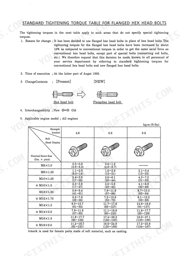
A torque from memory or a pressure from the wrong model can crack a part or hurt someone. This book gives you Kobelco's tightening torque tables and its own procedures for measuring engine speed and hydraulic pressure.
It covers the SK115SR-1E, SK135SR-1E, SK135SRLC-1E and SK135SRL-1E, and some specs change between them. The SK115SR-1E runs a 24 V / 30 A alternator and the SK135 machines run 24 V / 50 A. Confirm your model so you order the right part the first time.
What's Inside This Kobelco SK115SR-1E, SK135SR-1E, SK135SRLC-1E, SK135SRL-1E Manual
| System | Pages | Key Topics |
|---|---|---|
| Outline | 6-11 | General Precautions for Making Repairs, International Unit Conversion System |
| Specification | 12-33 | Names of Components, General Dimensions, Weights of Components, Specifications and Performance, Types of Crawler and Bucket, Combinations of Attachment |
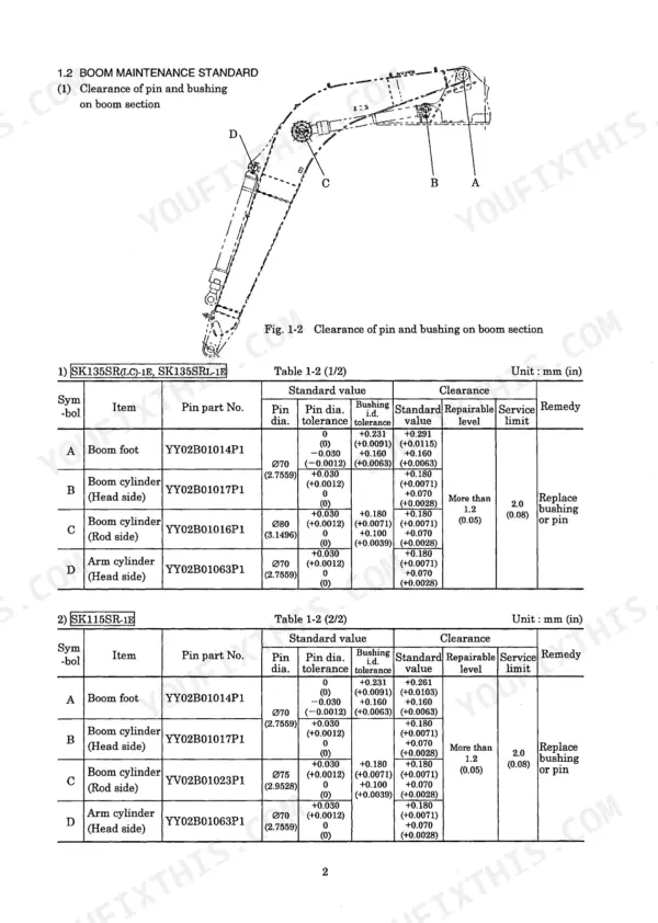
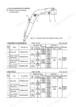
| Attachment Dimension | 34-51 | Boom, Arm and Bucket Dimensional Drawings and Maintenance Standards |
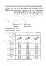
| Tools | 52-68 | Tightening Torques for Capscrews, Nuts and Sleeves, Screw Sizes, Plugs, Special Spanner for Tube, Special Tools, Screw Locking and Sealing Compounds, Lifting Jigs and Boom Foot Pin Pulling Tools |
| Standard Maintenance Time Schedule | 69-80 | Standard Maintenance and Replacement Times by Component Group, Attachment, Cab & Guard, Swing Frame, Standard Working Time Table |
| Maintenance Standard and Test Procedure | 81-104 | Performance Inspection Standard Table, Measurement of Engine Speed and Hydraulic Pressure, Travel, Swing and Attachment Performance Tests, Swing Bearing, Parking Brake Checks |
| Mechatro Control System | 105-124 | Mechatro Control System Summary, Boom Raise Conflux, Mechatro Controller, Self Diagnosis and Service Diagnosis Displays on the Gauge Cluster |
| Hydraulic System | 125-200 | Hydraulic Circuits and Components by Spec (EU STD, Dozer, Boom and Arm Safety, Extra, N&B), Color Coding Standard, Neutral and Travel Circuits, Hose Clipping Drawings |
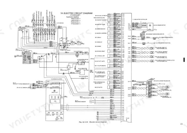
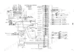
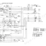
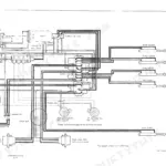
| Electric System | 201-244 | Electric Circuit Diagram, Electrical Equipment List, Harness List and Harness Drawings |
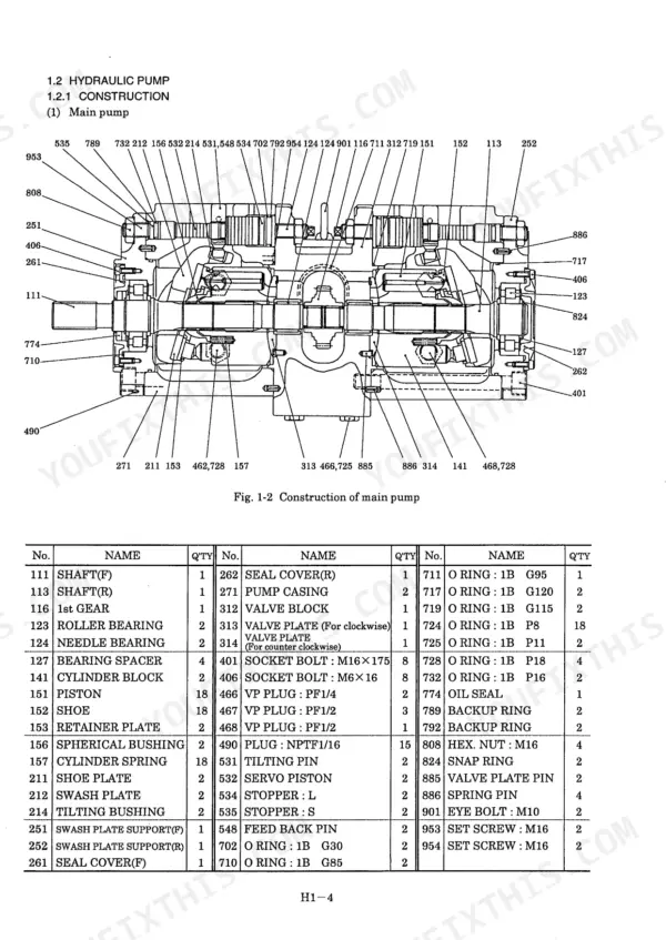
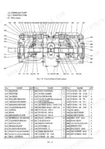
| Components System | 245-380 | Hydraulic Pump and Regulator, Pilot Valves (ATT and Travel), Control Valve, Swing Motor Unit, Travel Motor, Swivel Joint, Hydraulic Cylinder, Dozer Control Valve, List and Specification of Electric Equipment |
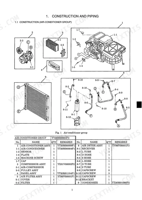
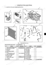
| Air-Conditioner System | 381-416 | Construction and Piping, A/C Controller Wiring Diagram and Connectors, Troubleshooting |
| Disassembling and Assembling: Explanation | 417-419 | How the Disassembly Chapters Are Laid Out, Indication of Tightening Torques |
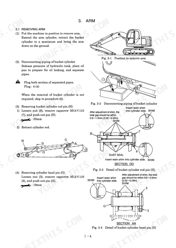
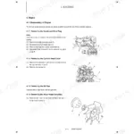
| Attachment | 420-454 | Removing and Installing Bucket, Arm and Boom, Cylinder Disassembly and Assembly |
| Upper Structure | 455-604 | Removing and Installing the Cab, Operator Seat, Battery, Counterweight, Guards, Air Cleaner, Muffler, Fuel Tank, Pump, Radiator and Oil Cooler, Control Valves, Pilot Valves, Swing Motor, Swivel Joint, Upper Frame; Disassembly of Pump, Control Valve and Pilot Valve |
| Travel System | 605-741 | Crawler, Upper and Lower Rollers, Front Idler, Travel Motor Removal, Installation and Disassembly |
| Troubleshooting: Mechatro Control | 742-750 | Outline, Actuator Table, Troubleshooting Outline for the Mechatro System |
| Troubleshooting: Hydraulic | 751-777 | Trouble Diagnosis Table and Hydraulic Troubleshooting, No Operation Is Possible, All Attachment Motions Are Slow, Only the Bucket Motion Is Slow, Only the Boom Raise Motion Is Slow, Only Arm Out Operation Is Slow, Boom Up Operating Power Is Poor, Arm in Power Is Poor |
| Troubleshooting: Electric | 778-798 | Trouble Diagnosis Table, Self Diagnosis Table, Service Diagnosis Table, Electrical Troubleshooting Flowcharts |
| Troubleshooting: Engine | 799-808 | Engine Trouble Diagnosis Table and Troubleshooting Flowcharts, Starter Does Not Run, Starter Turns But Engine Is Hard to Start, E/G Output Is Insufficient, Overheat, E/G Does Not Stop |
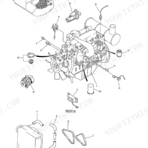
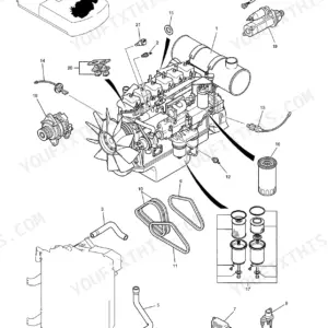
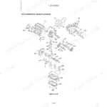
| Engine | 809-963 | Isuzu Engine: General, Engine Proper, Lubrication and Cooling Systems, Troubleshooting, Special Tools, Repair Standard, Turbocharger, Starter, Alternator |
| Installation Procedures for Optional Attachment | 964-1022 | Mounting the Breaker and Nibbler: Additional Parts, Modification Items, Piping and Electrical Installation |
Quick Reference Specifications
| Specification | Value | Page |
|---|---|---|
| Engine model | Isuzu BB-4BG1T | p. 25 |
| Engine type | Water-cooled, 4-cycle direct injection, turbocharged | p. 25 |
| Cylinders - bore x stroke | 4 - 105 mm x 125 mm (4.13 in x 4.92 in) | p. 25 |
| Total displacement | 4,329 cc (264 cu·in) | p. 25 |
| Rated output / rotation speed | 62.5 kW (85 PS) / 2,050 rpm (SK135SR-1E, SK135SRLC-1E, SK135SRL-1E) / 58.8 kW (80 PS) / 2,050 rpm (SK115SR-1E) | p. 25 |
| Maximum torque / rotation speed | 32.4 kgf·m (235 lbf·ft) / 1,600 rpm (SK135SR-1E, SK135SRLC-1E, SK135SRL-1E) / 30.0 kgf·m (217 lbf·ft) / 1,600 rpm (SK115SR-1E) | p. 25 |
| Starter | 24 V / 4.5 kW | p. 25 |
| Alternator | 24 V / 50 A (SK135SR-1E, SK135SRLC-1E, SK135SRL-1E) / 24 V / 30 A (SK115SR-1E) | p. 25 |
| Swing speed | 11.7 rpm (SK135SR-1E, SK135SRLC-1E, SK135SRL-1E) / 11.4 rpm (SK115SR-1E) | p. 25 |
| Travel speed (1-speed / 2-speed) | 2.8 / 5.1 km/h (1.7 / 3.2 mph) (SK135SR-1E, SK135SRLC-1E, SK135SRL-1E) / 3.5 / 6.0 km/h (2.2 / 3.7 mph) (SK115SR-1E) | p. 25 |
| Gradeability | 70% (35°) | p. 25 |
| Fully equipped weight | 13,700 kg (30,200 lbs) (SK135SR-1E) / 13,900 kg (30,640 lbs) (SK135SRLC-1E) / 15,700 kg (34,610 lbs) (SK135SRL-1E) / 11,900 kg (26,230 lbs) (SK115SR-1E) | p. 25 |
Kobelco SK115SR-1E, SK135SR-1E, SK135SRLC-1E, SK135SRL-1E Common Problems This Manual Covers
Engine runs but no motions operate
Follow the 'no motions operate' flowchart in the electrical troubleshooting section. It has you check for 24V across the white/blue and black wires at the lever lock solenoid. A blown Fuse No.15 is one of the findings it covers. Use the electric circuit diagram and harness drawings to trace the wiring.
Manual Section: Troubleshooting: Electric p. 784Only the bucket is slow, or only boom up is slow
If only the bucket is slow, or only boom up speed drops, the electrical troubleshooting flowcharts send you to inspect the ATT pilot valve. The Components System chapter explains the ATT pilot valve. The Upper Structure chapter covers removing, installing and disassembling the pilot valves.
Manual Section: Troubleshooting: Electric p. 786Setting up to tear down a boom, arm or bucket cylinder
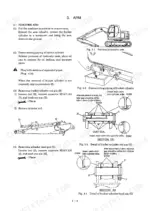
Read the cylinder disassembly preparation notes before you start. They deal with separating the cylinder tube from the piston rod and stress that the working area has to be long enough. The Attachment chapter then covers removing the bucket, arm and boom, plus cylinder disassembly and assembly.
Manual Section: Attachment p. 434Fault diagnosis started without the basic facts
The troubleshooting outline tells you to verify the model, serial number and situation of the trouble before anything else. It then works toward the cause in the order the trouble occurred. Use it with the actuator table and the troubleshooting outline in the mechatro troubleshooting chapter.
Manual Section: Troubleshooting: Mechatro Control p. 744Frequently Asked Questions
The engine keeps running after I turn the key off. What does the manual check?
The engine troubleshooting flowcharts cover this exact symptom. They have you check the governor motor link connecting bolts, and they also point to replacing the battery relay. Follow the flowchart rather than swapping parts at random. p. 808
Can the machine show me the faults it has logged?
Yes. The mechatro controller stores and displays the troubles it detects through its self diagnosis. You read them on the gauge cluster multi-display, which also has a separate service diagnosis display. The electric troubleshooting chapter has a self diagnosis table and a service diagnosis table that explain what you are looking at. p. 119
How do I read engine rpm without hooking up a separate tachometer?
Bring the engine up to high idle and press the screen change switch once. Engine rpm then shows on the gauge cluster multi-display. Check your reading against the performance inspection standard table in the maintenance and test chapter. p. 88
How do I test whether the pump and travel motor are delivering proper travel performance?
Measure travel sprocket revolution with a stroboscope. The manual uses this test to confirm performance between the hydraulic pump and the travel motor. For reference, travel speed is 2.8 / 5.1 km/h on the SK135SR-1E, SK135SRLC-1E and SK135SRL-1E, and 3.5 / 6.0 km/h on the SK115SR-1E. p. 93
Do these machines have boom and arm lock valves and a swing parking brake?
Yes. The manual lists lock valves on the boom and arm among the hydraulic system features. It also lists an automatic swing parking brake that protects against swing drift on a slope. The maintenance and test chapter includes swing bearing and parking brake checks. p. 127
Reviews
There are no reviews yet.