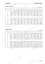
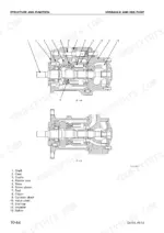
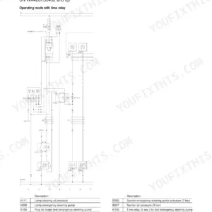
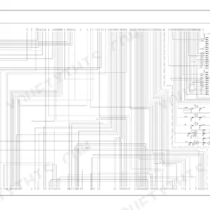
A D61 in the yard with a slipping steering brake and a final drive weeping oil needs answers, and the Komatsu D61EX-12, D61PX-12 shop manual PDF (SEBM036700) carries them across 617 pages of factory bulldozer data. Testing and adjusting fills roughly a quarter of the book, pairing the chassis standard value table with troubleshooting sequences that trace a fault from symptom to the failed component. Disassembly runs from engine removal through the torque converter, HSS motor, final drive and track rollers, while the maintenance standard section gives you wear limits for the bevel gear shaft, brakes and work equipment cylinders. Keep at least 50 mm between the output shaft and the ground during final drive work, and bring radiator hose clamps to 8.8 ± 0.5 Nm. A rebuild stalls when one number is missing. Search the text or jump by bookmark on screen, then print the sections your job calls for and let those pages get greasy on the bench.
What's Inside This Komatsu D61EX-12, D61PX-12 Manual
| System | Pages | Key Topics |
|---|
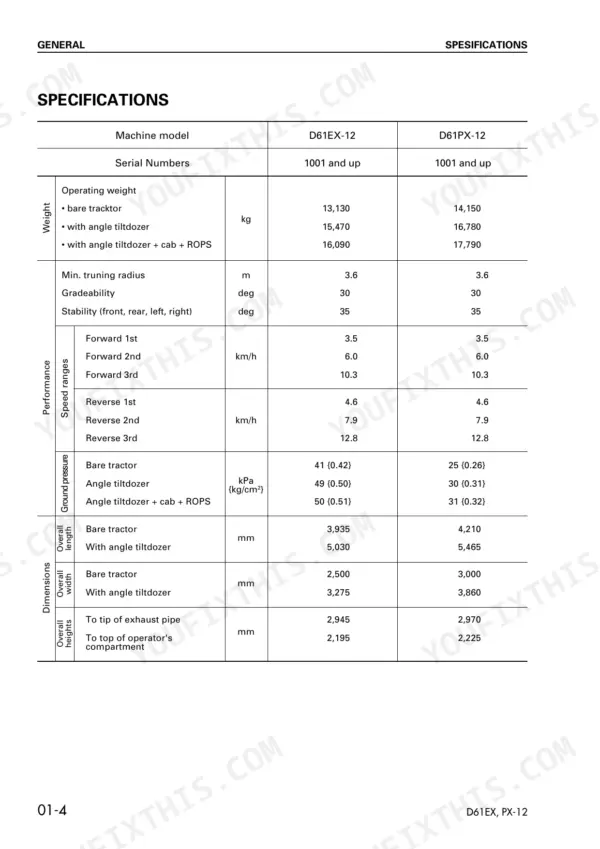
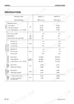
| General | 23-34 | Specification Drawing, Specifications, Weight Table, Table of Fuel, Coolant and Lubricants |
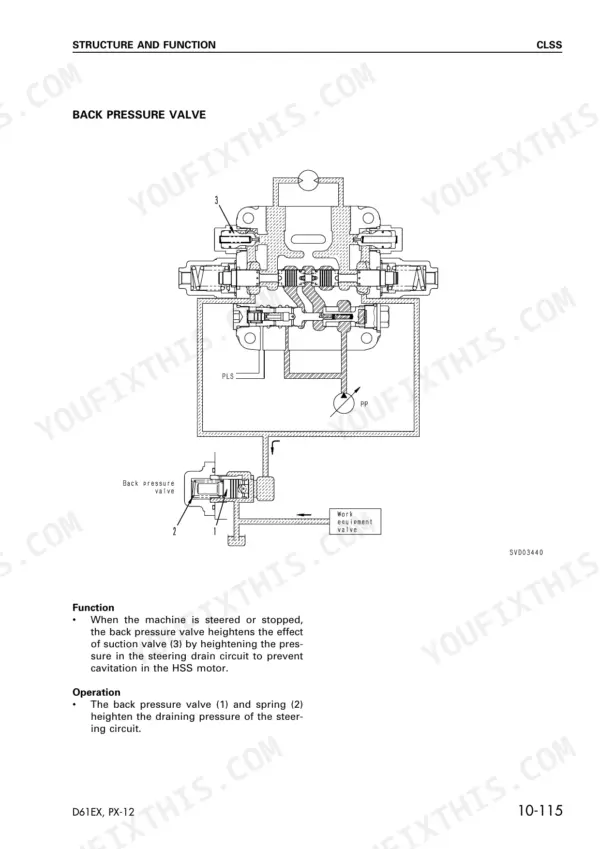
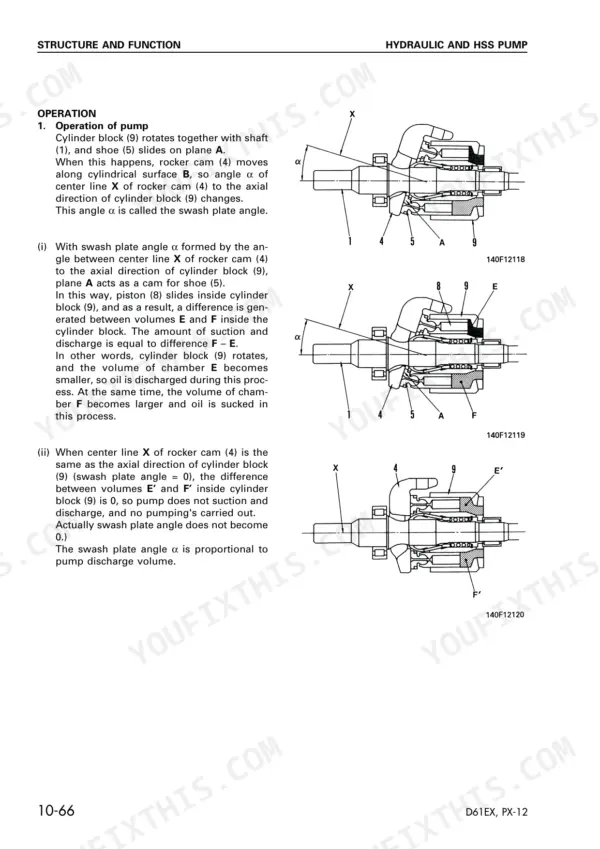
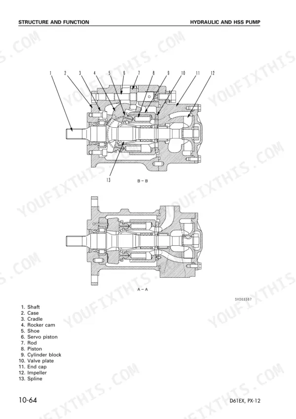
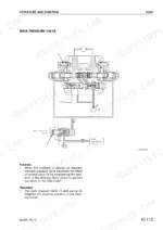
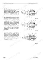
| Structure and Function | 35-165 | Power Train System, Transmission, Transmission Control Valve, Bevel Gear Shaft, HSS Steering, Steering Brake, Hydraulic and HSS Pump, Main Control Valve |
| Testing and Adjusting | 166-311 | Standard Value Table for Chassis, Troubleshooting |
| General Procedures and Engine | 312-330 | Manual Usage, Safety Precautions, Special Tools, Engine Removal and Installation, Radiator and Guard |
| Power Train Components | 331-390 | Radiator, Fuel Tank, Damper, PTO, Torque Converter, Transmission, Transmission Control Valve |
| Steering and Brake Systems | 391-427 | Steering Brake, HSS, Brake Valve, HSS Motor, Scavenging Pump, Power Train Oil Pump |
| Undercarriage and Track Components | 428-501 | Final Drive, Track Frame, Recoil Spring, Idler, Track Roller, Carrier Roller, Track Shoe, Pivot Shaft |
| Hydraulic System and Work Equipment | 502-560 | HSS and Hydraulic Pump, PPC Pump, Main Control Valve, Steering PPC Valve, Hydraulic Cylinders, Work Equipment, Floor Frame |
| Maintenance Standard | 561-609 | Bevel Gear Shaft, HSS Steering, Brake, Main Control Valve, Work Equipment Cylinder, Work Equipment |
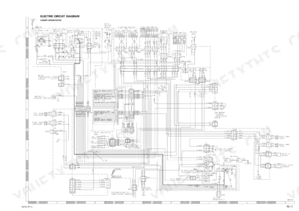
| Others | 610-617 | Electric Circuit Diagram |
Quick Reference Specifications
| Specification | Value | Page |
|---|
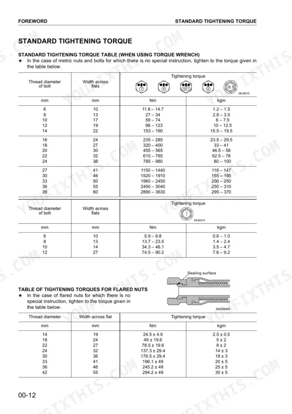
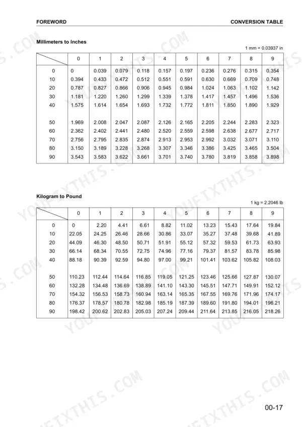
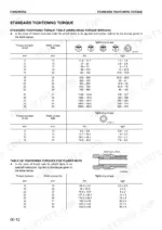
| Standard Tightening Torque (Metric Nuts and Bolts) | 11.8 – 14.7 Nm (1.2 – 1.5 kgm) to 2890 – 3630 Nm (295 – 370 kgm) | p. 12 |
| Tightening Torques for Flared Nuts | 24.5 ± 4.9 Nm (2.5 ± 0.5 kgm) to 294.2 ± 49 Nm (30 ± 5 kgm) | p. 12 |
| Radiator Fin pitch | 4.0 mm | p. 36 |
| Radiator hose clamp torque | 8.8 ± 0.5 Nm {0.9 ± 0.05 kgm} | p. 330 |
| Distance between output shaft and ground | at least 50 mm | p. 431 |
| Transmission case oil capacity | 69 L | p. 428 |
| Final drive mounting bolt torque | 490 – 608 Nm {50 – 62 kgm} | p. 430 |
| Guard mounting bolt torque | 235 – 285 Nm {23.5 – 29.5 kgm} | p. 430 |
| Track roller assembly weight | 45 kg (1 piece of single type), 52 kg (1 piece of double type) | p. 459 |
| Track roller mounting bolt torque | 230 – 289 Nm | p. 459 |
| Lubricator torque | 58.8 – 88.2 Nm | p. 453 |
| Support mounting bolt torque | 235 – 285 Nm | p. 453 |