

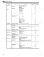
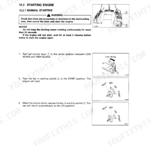
Drive unit, electromagnetic brake, hydraulic system, mast uprights, reach pantograph: the 209-page Komatsu FR15K-3, FR18K-3, and FR23K-3 service manual PDF, factory number SM151, takes each system on these electric AC stand-up rider narrow aisle reach trucks from disassembly through inspection to reassembly. Hydraulic circuit diagrams trace oil flow from pump through control valve to the lift, reach, and tilt cylinders. When a cylinder drifts or the lift goes spongy, troubleshooting tables point you to the cause, and chain inspection procedures show how to catch stretch before a worn link becomes a dropped load. Fill the hydraulic tank with 18.6 liters, then torque the drive unit installation bolts to 284-333 N·m. Second shift, one dead reach truck, nobody left to ask: that is when this book earns its keep. Bookmarked and text-searchable, the PDF walks you from fault to a truck that lifts again.
What's Inside This Komatsu FR15K-3, FR18K-3, FR23K-3 Manual
| System | Pages | Key Topics |
|---|---|---|
| Introduction and Safe Work | 1-14 | Electric AC-powered Stand-Up Rider, Narrow Aisle Single Reach, Double Reach, Models Covered, Maintenance Facility Requirements, Maintenance Workshop, Work Clothing, Tools and Gauges |
| General Specifications | 15-20 | Chassis Specifications, Mast Specifications, Performance Specifications, Motor Specifications, Battery Specifications |
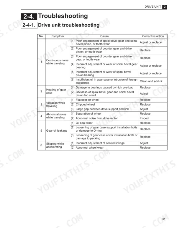
| Drive, Caster and Steering | 21-45 | Drive Unit Parts, Gear Disassembly, Gear Assembly, Gear Inspection, Drive Unit Troubleshooting, Caster Wheel Removal, Caster Spring Adjustment, Link Pin Inspection |
| Brake System | 46-55 | Brake Linkage Disassembly, Pedal Bracket, Pedal Pin, Micro Switch, Brake Pedal, Pedal Pad, Electromagnetic Brake, Spline Hub |
| Hydraulic System | 56-71 | Hydraulic Circuit Diagram, Oil Piping Replacement, Hydraulic Hose, Hydraulic Pipe, Hydraulic Pump Removal, Cushion Bracket, Motor Bracket, Pump Installation |
| Motors | 72-85 | Traction Motor, Hydraulic Motor, EPS Motor, Rotor Component, Armature Component, Motor Troubleshooting |
| Electrical Equipment | 86-103 | Fet Module, Capacitor, Mpu Board, Heat Sink, Current Sensor, EPS Controller, EPS/Dsp Board, Grommet |
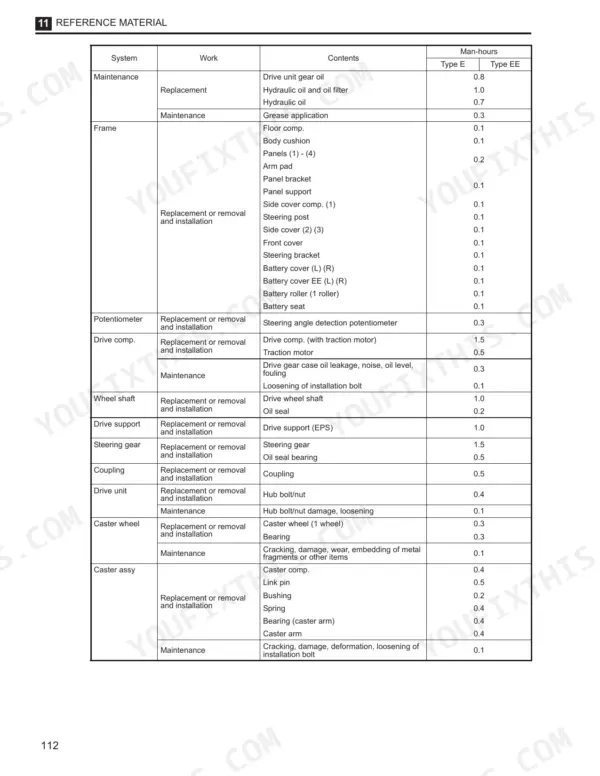
| Reference, Installation and Periodic Maintenance | 104-115 | Standard Maintenance Work Time, Maintenance System, Man-Hours, Truck System Requirements, Mast Installation, Mast Inspection, Daily Inspection, 250-Hour Inspection |
| Mast Uprights | 116-149 | Upright Description, Outer Upright Assembly, Intermediate Upright Assembly, Preparation, Upright Disassembly, Cable and Chain Sheaves, Free Lift Cylinder, Elongation |
| Reach Pantograph | 150-209 | Electrical Plug, Hydraulic Hoses, Chain Anchor Pins, Rail Assemblies, Chain Hoist, Fork Carriage, Pantograph Arm Rollers, Thrust Pads |
Quick Reference Specifications
| Specification | Value | Page |
|---|---|---|
| Drive unit installation bolts tightening torque | 284 - 333 N·m | p. 26 |
| EPS gear box gear oil volume | 0.35 L | p. 29 |
| Cold storage (CS) type oil | ISO VG15 (SAE No. 10W) | p. 67 |
| Quantity of oil | 18.6 L | p. 63 |
| FET module main terminal part (M6) tightening torque | 3.5 - 4.5 N·m | p. 94 |
| Main contactor main terminal part (M8) tightening torque | 12.7 - 14.7 N·m | p. 99 |
| backrest capscrews torque | 145 ft.-lbs. (195 Nm) | p. 113 |
| Torque jam nuts to adjustment nuts | 100 - 200 Nm (74 - 148 Ft-Lbs) | p. 128 |
| Panel (1) installation bolts torque | 4.7 N·m | p. 24 |
| Drive unit installation bolts torque | 284 - 333 N·m | p. 28 |
| EPS gear box oil volume | 0.35 L | p. 29 |
| Gearbox oil volume | 3.1 L | p. 30 |
Komatsu FR15K-3, FR18K-3, FR23K-3 Common Problems This Manual Covers
Komatsu FR15K-3 reach truck powers up but will not travel or lift, drive cuts out intermittently
Check battery connectors and cables for corrosion and heat damage first. Test the main fuse and inspect the main contactor tips for pitting, following the contactor removal steps on page 97. Retorque the contactor M8 main terminals to 12.7 to 14.7 N·m; a loose lead bar mimics a dead controller under load.
Manual Section: Main Contactor and Fuse p. 97Lift and tilt functions turn slow, weak, or jerky once the hydraulic oil warms up
Check hydraulic oil level and condition; dark or milky oil means drain the tank and refill with 18.6 L of fresh oil. Clean the suction filter and replace the return filter element. Then verify relief pressure reaches 19.5 MPa using the control valve troubleshooting steps on page 71, and adjust if low.
Manual Section: Control Valve p. 71Steering error codes appear, wheel feels notchy, or truck steers hard at low speed
Inspect the EPS sensor gear and harness connectors for corrosion and chafing, then work through the steering assy troubleshooting table on page 45. Check the EPS encoder wiring at the control panel for damage. If the gearbox is noisy or dry, refill the EPS gear box with 0.35 L of gear oil before condemning the EPS controller.
Manual Section: Steering Assy p. 45Travel feels sluggish, electromagnetic brake drags, or brake will not release fully
Verify the brake releases electrically before pulling parts; the brake system troubleshooting table on page 55 covers release, force, and noise faults. Check the micro switch adjustment on the brake pedal linkage. Adjust electromagnetic brake clearance per the procedure, then torque the brake assy installation bolts to 26.5 to 32.4 N·m.
Manual Section: Brake p. 55Forks drift down under load, lift action feels spongy or jerky through the mast
Test for drift with a rated load and work the troubleshooting chart on page 115; steady drift usually points to leaking lift cylinder packing or a control valve fault. Bleed air from the cylinders to cure spongy action. After any chain length adjustment, torque the jam nuts against the adjustment nuts to 100 to 200 N·m.
Manual Section: Troubleshooting Chart (Mast) p. 115Frequently Asked Questions
What is the hydraulic system relief pressure on the Komatsu FR15K-3, FR18K-3, FR23K-3?
The hydraulic relief pressure is 19.5 MPa (200 kgf/cm²), set at the FER-70(E/EE) control valve; the specification is printed on page 39 of the manual. p. 56
What is the tightening torque for the drive unit installation bolts on the Komatsu FR15K-3, FR18K-3, FR23K-3?
The tightening torque for the drive unit installation bolts is 284 - 333 N·m. p. 28
What is the recommended oil for the hydraulic system under standard conditions?
For standard type models, the recommended oil is ISO VG32 or an equivalent product. p. 63
What is the tightening torque for the main contactor terminal part (M8) on the Komatsu FR15K-3, FR18K-3, FR23K-3?
The tightening torque for the main contactor terminal part (M8) is 12.7 - 14.7 N·m. p. 99
What is the standard clearance for the brake assembly on a Komatsu FR15K-3, FR18K-3, FR23K-3?
The initial setting for the brake assembly clearance is 0.3 mm, with a tolerance range of 0.25 - 0.40 mm and a limit value of 0.72 mm. p. 54
Is this Komatsu FR15K-3 Service Manual a digital download?
All 209 pages arrive as one searchable PDF at checkout. Read it at the desk, then take the phone out to the machine.
Can I print just the pages I need from this Komatsu FR15K-3 manual?
Yes. Print the pages or sections you need for your own shop use. Any standard printer works.


Reviews
There are no reviews yet.