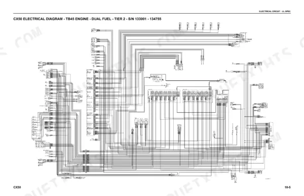
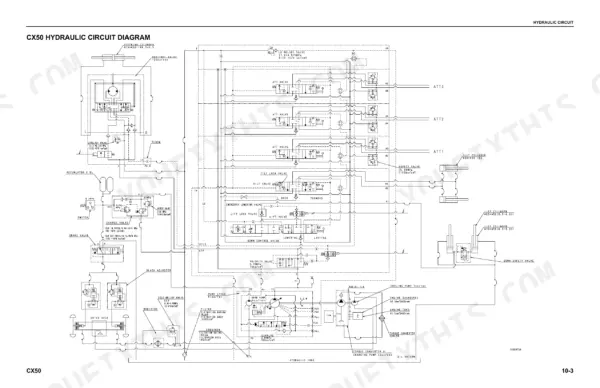
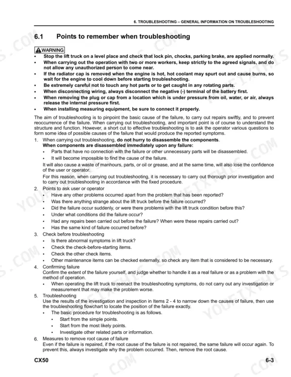
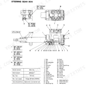
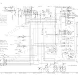
Eight forklift trucks, the gasoline FG and diesel FD variants running the EBT-TB45-2A/3A or SAA4D95LE-5-A engine, are covered by this 680-page Komatsu FG40ZTU-10 to FD50ATU-10 series service manual PDF, OEM ID SM203. CX50 electrical diagrams split by fuel type and serial break sit beside the hydraulic circuit and piping diagrams for the CLSS load sensing system, steering, brakes and attachments. Troubleshooting runs from ISO controller flash codes through E-mode electrical faults to the H-mode failure table, while disassembly covers the Torqflow transmission, torque converter, differential, lift and tilt cylinders, plus U.S.-built 2-stage and 3-stage masts. Refill the transmission case with 12 L at replacement, and look for clutch pressure of 1.01 to 1.25 MPa when testing the power train. When your truck cannot travel, start at fault E-3. Bookmarks and a live text layer take you straight to the section you want, whether that is inching pedal adjustment or the yearly inspection criteria.
What's Inside This Manual
| System | Pages | Key Topics |
|---|
| Specifications | 53-62 | Dimensional Diagram, Diesel Engine Lift Truck with SAA4D95LE-5-A Engine, Gasoline Engine Lift Truck with Ebt-TB45-2A/3A, Weight Table, Lubricants |
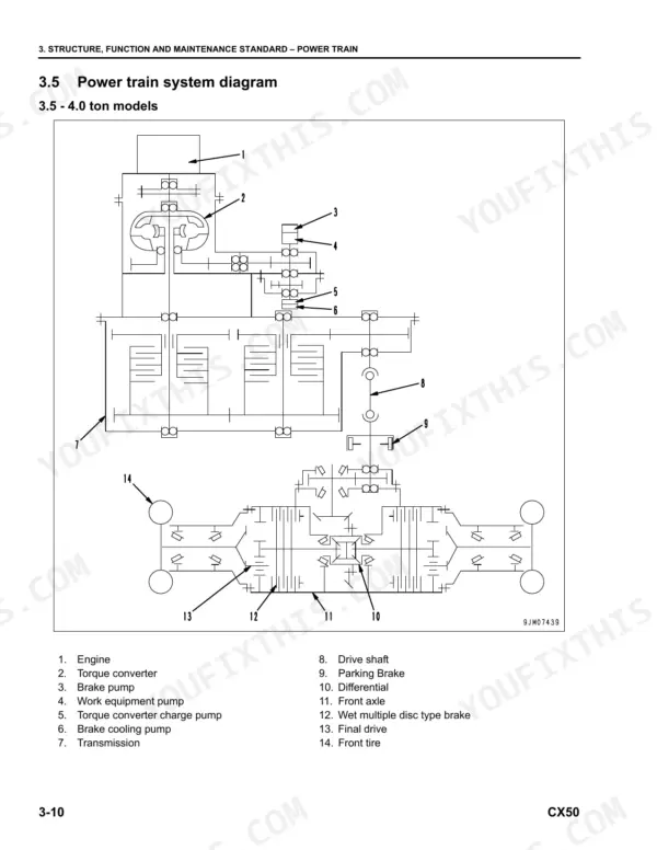
| Structure, Function and Maintenance Standard | 63-246 | Engine and Cooling System (Cooling System - Diesel Engine, Cooling System - Gasoline Engine, Brake Cooling System Hydraulic Piping Diagram) |
| Standard Value Table | 247-252 | Lift Truck with SAA4D95LE-5-A Engine, Lift Truck with Ebt-TB45-2A/3A Engine |
| Testing and Adjusting | 253-284 | Check of Troubleshooting Software Functions and Failure Codes, Hydraulic Piping Pressure Release Procedure, Engine Oil and Engine Oil Filter, Fuel Filter, Cleaning of Radiator |
| Troubleshooting | 285-428 | Failure Codes: ISO Controller (Display by ISO Controller, [[!]: 1 Flashing, [N]: Flashing) |
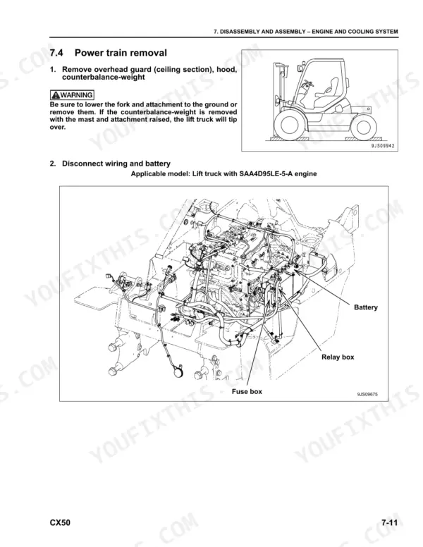
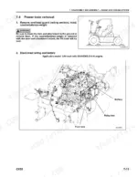
| Disassembly and Assembly | 429-542 | Engine and Cooling System (Power Train: Removal, Installation) |
| U.S. Manufactured Masts | 543-646 | 80D/100D/110D-Ms 2-Stage Masts (Introduction, Installation Instructions, Periodic Maintenance, Troubleshooting, Service) |
| Yearly Inspection Criteria | 647-664 | Inspection Criteria Table |
| Diagrams and Drawings | 665-680 | Hydraulic Circuit (CX50 Hydraulic Circuit Diagram) |
Quick Reference Specifications
| Specification | Value | Page |
|---|
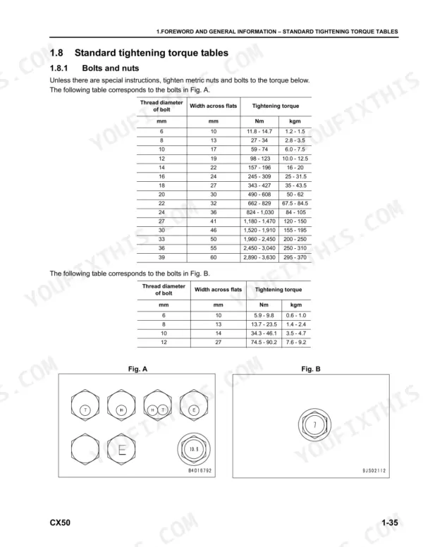
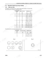
| O-ring boss plugs (Nominal No. 08) | 5.88 - 8.82 Nm | p. 44 |
| O-ring boss plugs (Nominal No. 10) | 9.8 - 12.74 Nm | p. 44 |
| Engine oil pan capacity (4 ton Compact model) | 11 L | p. 60 |
| Torqflow transmission case capacity (Replacement) | 12 L | p. 60 |
| Clutch pressure | 1.01 - 1.25 MPa {10.3 - 12.7 kgf/cm2} | p. 96 |
| Main relief valve cracking pressure | 1.13 ± 0.12 MPa {11.5 ± 1.2 kgf/cm2} | p. 249 |
| Coolant amount (SAA4D95LE-5-A) | 9 liter | p. 249 |
| Coolant amount (EBT-TB45-2A/3A) | 16 liter | p. 251 |
| Starting switch rated load B-M | 35A | p. 211 |
| Starting switch rated load B-G | 2A | p. 211 |
| Air bleeding plug (3) torque | 7.8 - 9.8 Nm | p. 262 |