
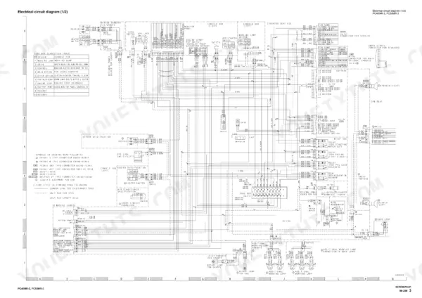
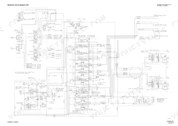
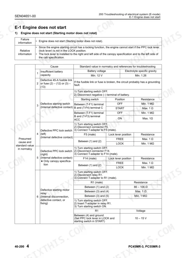
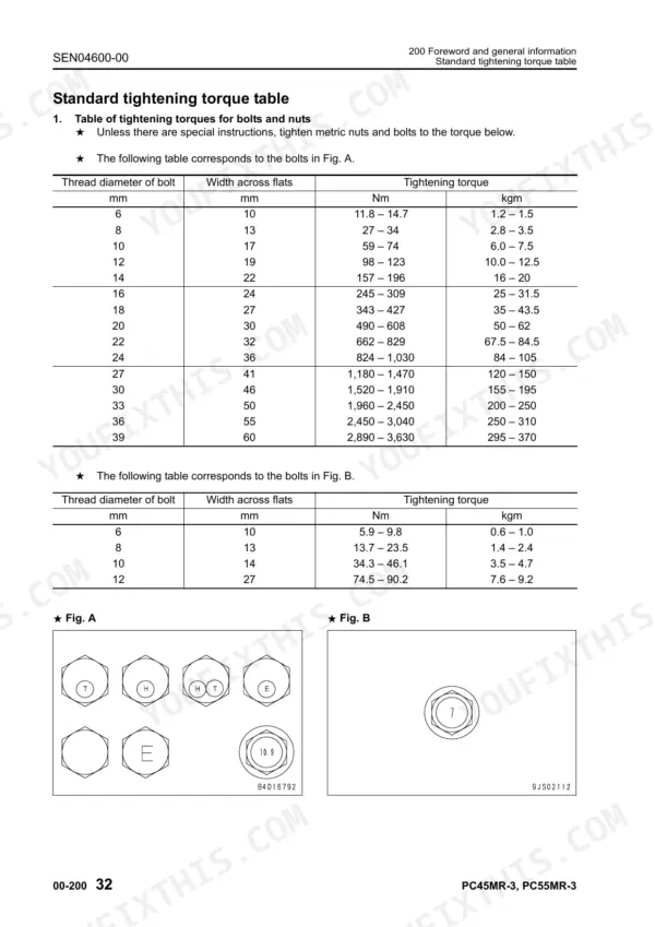
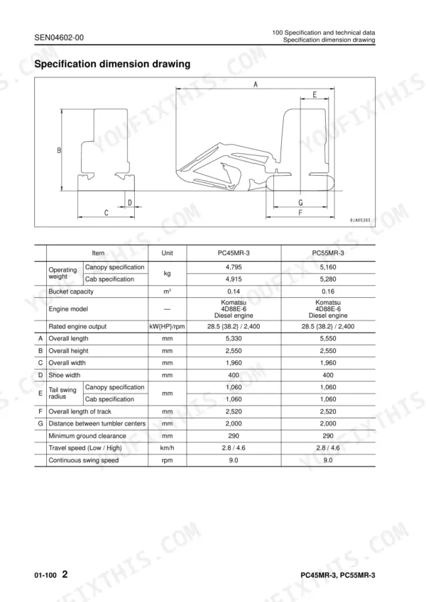
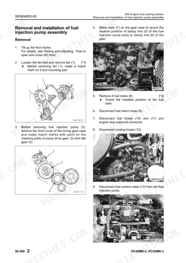
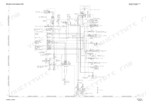
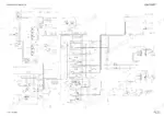
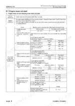
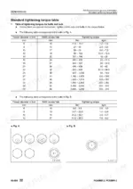
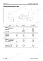
Track shoe tension adjustment, swing machinery rebuilds and engine and hydraulic pump removal are all set out in this 572-page Komatsu PC45MR-3 shop manual PDF (OEM ID SEN04597-02), which also covers the PC55MR-3 hydraulic excavator. The hydraulic circuit diagram lays out the CLSS system, and the electrical circuit diagram comes paired with a connector list and stereogram for locating each plug. Fault tables run in E-mode electrical, H-mode hydraulic and S-mode engine sequences, so H-14 Machine Deviates During Travel leads directly to its own checks. Refill the engine oil pan with 7.5 L (8.1 L total capacity), and torque standard 6 mm bolts to 11.8 to 14.7 Nm. If your next job is a track roller or idler rebuild, the special tool list and coating materials list show what to order first. Bookmarks jump between sections. A searchable text layer lets you confirm the exact assembly name before the order goes in.
What's Inside This Komatsu PC45MR-3, PC55MR-3 Manual
| System | Pages | Key Topics |
|---|---|---|
| Index and Foreword | 2-53 | Composition of Shop Manual, Safety Notice, Standard Tightening Torque Table, Conversion Table |
| Specification | 54-69 | Specification and Technical Data (Specification Dimension Drawing, Working Range Drawing, Specifications, Weight Table, Table of Fuel, Coolant and Lubricants) |
| Structure, Function and Maintenance Standard | 70-215 | Engine and Cooling System (PTO), Power Train (Swing: Circle, Machinery) |
| Standard Value Table | 216-235 | Standard Service Value Table (Engine Related Parts, Chassis Related Parts) |
| Testing and Adjusting | 236-295 | Tools for Testing, Adjusting, And Troubleshooting, Testing Engine Speed, Testing Exhaust Gas Color, Testing and Adjusting Valve Clearance, Testing Compression Pressure |
| Troubleshooting | 296-465 | Troubleshooting of Electrical System (Before Carrying Out Troubleshooting of Electrical System, E-1 Engine Does Not Start, E-2 Engine Does Not Stop) |
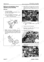
| Disassembly and Assembly | 466-559 | Engine and Cooling System (Removal Installation: Fuel Injection Pump Assembly, Radiator Assembly, Hydraulic Oil Cooler Assembly, Engine and Hydraulic Pump Assembly) |
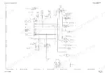
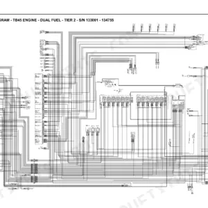
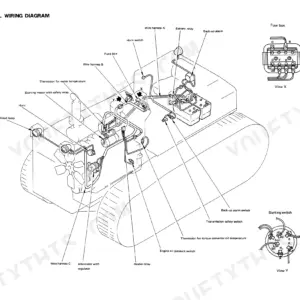
| Diagrams and Drawings | 560-572 | Hydraulic Diagrams and Drawings (Hydraulic Circuit Diagram), Electrical Diagrams and Drawings (Electrical Circuit Diagram, Connector List and Stereogram) |
Quick Reference Specifications
| Specification | Value | Page |
|---|---|---|
| All Models | ||
| Standard tightening torque for 6mm bolt | 11.8 – 14.7 Nm | p. 43 |
| Tightening torque for 102, 107 and 114 engine series eye joints (6mm) | 8 ± 2 Nm | p. 46 |
| Tightening torque for 102, 107 and 114 engine series eye joints (8mm) | 10 ± 2 Nm | p. 46 |
| Engine oil pan capacity | 8.1 L | p. 67 |
| Engine oil pan refill capacity | 7.5 L | p. 67 |
| Boom relief pressure | 26.5 ± 0.98 MPa {270 ± 10 kg/cm2} | p. 220 |
| Arm relief pressure | 26.5 ± 0.98 MPa {270 ± 10 kg/cm2} | p. 220 |
| Alternator terminal voltage | 10 – 15 V | p. 447 |
| Battery relay terminal voltage | 10 – 15 V | p. 448 |
| Rated engine output | 28.5 kW {38.2 HP} / 2,400 rpm | p. 55 |
| PC45MR-3 | ||
| Operating weight (Canopy) | 4,795 kg | p. 55 |
| PC55MR-3 | ||
| Operating weight (Canopy) | 5,160 kg | p. 55 |
Komatsu PC45MR-3, PC55MR-3 Common Problems This Manual Covers
Komatsu PC45MR-3 PC55MR-3 speed or power of whole work equipment, travel, swing, and blade is low
Check hydraulic oil level and type, then the hydraulic oil strainer and filter for clogging per page 299. Measure relief pressures against the page 220 standard values; each turn of the work equipment main relief valve shifts 12.6 MPa (page 258). Before testing, lower the work equipment, stop the engine, slowly loosen the hydraulic filler cap and set the lock lever to LOCK (page 256). With no swing holding brake fitted, lock the machine securely with the work equipment (page 258).
Manual Section: Troubleshooting of Hydraulic and Mechanical System (H-mode) p. 303Monitor panel charge level caution turns on while the machine is operating
Check battery, alternator and starting motor terminals and wiring for looseness or corrosion, tightening or replacing as needed per page 299. Measure battery voltage with the engine stopped against 10 to 15 V, then alternator voltage after several minutes at half throttle or above against 13.5 to 14.5 V. When disconnecting wiring, always disconnect the battery negative terminal first (page 297).
Manual Section: E-7 Charge Level Caution Is Turned on p. 299Engine cranks but exhaust smoke does not come out and engine will not start
Check fuel level and fuel type, clean and drain impurities from the fuel, and replace a clogged fuel filter cartridge per page 299. Verify battery voltage reads 10 to 15 V with the engine stopped, and listen for the battery relay operating sound as the starting switch turns ON and OFF. Then run the S-2 starting checks listed on page 303.
Manual Section: Troubleshooting of Engine (S-mode) p. 303Engine oil pressure caution lamp lights up on the monitor and oil pressure lowers
Check engine oil level in the oil pan and confirm the oil type, then replace the engine oil filter if it is clogged, per page 299. The oil pan holds 8.1 L (page 67). If level and filter check good, follow S-12 for low oil pressure (page 303) and E-6 for the caution circuit (page 304).
Manual Section: E-6 Engine Oil Pressure Caution Is Turned on p. 304Engine coolant temperature rises too high and the coolant temperature gauge reads overheating
Wait for the engine to cool before removing the radiator cap, since hot coolant may spurt out and cause burns (page 297). Check coolant level and add coolant as needed per page 299; the cooling system holds 8.5 L (page 67). Check for oil leakage while you are there, then work through S-14 for overheating from the fault list on page 303.
Manual Section: Troubleshooting of Engine (S-mode) p. 303Travel speed does not change and 2nd travel speed is not selected
Check for blown or corroded fuses, discolored or burnt wiring, and water leaking on connectors or terminals, then disconnect and dry any wet connectors per page 299. Disconnect the battery negative terminal first before disconnecting any wiring (page 297). Then follow E-12 for the electrical side and H-17 for travel speed change, both listed on page 304.
Manual Section: E-12 2nd Travel Speed Is Not Selected p. 304Frequently Asked Questions
What causes slow or weak hydraulics on a PC45MR-3 or PC55MR-3?
Slow or weak hydraulics can be caused by a malfunction of the PPC basic pressure lock solenoid valve, a defective adjustment or malfunction of the control circuit relief valve, a clogged suction strainer, or a defective control pump. For detailed troubleshooting steps, refer to the 'H-1 Speed or power of whole work equipment, travel, swing, and blade is low' section on page 405. p. 405
What is the standard tightening torque for the cylinder head bolts on a PC45MR-3 boom cylinder?
The standard tightening torque for the cylinder head bolts on a PC45MR-3 boom cylinder is 736 ± 73.6 Nm {75 ± 7.5 kgm}. p. 109
What is the standard valve clearance for the engine on a PC45MR-3 or PC55MR-3?
The standard valve clearance for both the intake and exhaust valves on the PC45MR-3 and PC55MR-3 engine is 0.20 mm. p. 217
What is the specified capacity for the hydraulic tank on a PC45MR-3 or PC55MR-3?
The specified capacity for the hydraulic tank on these models is 33 liters. p. 96
How do I bleed air from the hydraulic pump?
To bleed air from the pump, loosen air bleeder (1) until oil without air flows out, then tighten it to 8.8 ± 1 Nm {0.9 ± 0.1 kgm}. After this, run the engine at low idle for about 10 minutes. Note: Remove the triangular cover from the left rear of the machine to access the bleeder. p. 277
What format is this Komatsu PC45MR-3 manual in?
Instant PDF download. You get the full 572-page searchable Shop Manual immediately after payment. Open it on your laptop, tablet, or phone right in the shop.
Can I print a copy of this Komatsu PC45MR-3 Shop Manual for the shop?
Yes. Many mechanics print the section they need for their own shop and bring it to the bench.


