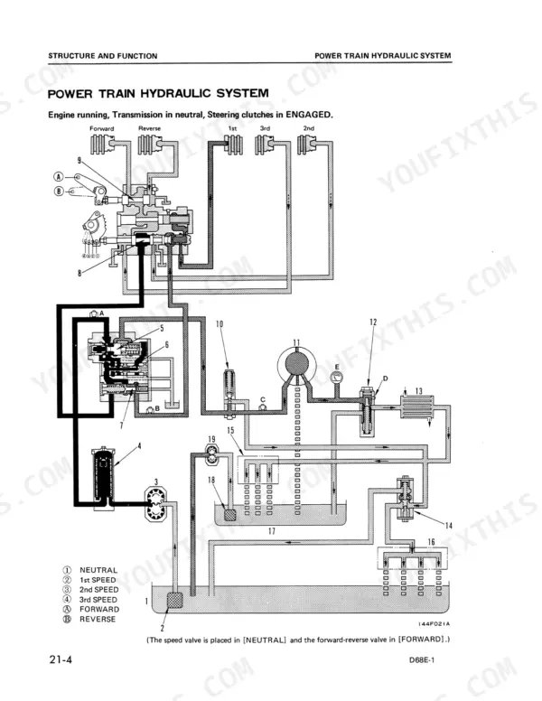
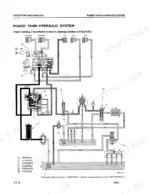
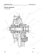
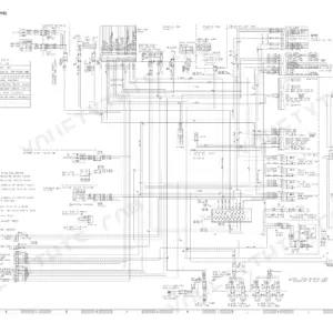
Undercarriage rebuilds are the most involved job in this 409-page Komatsu D68E-1 shop manual PDF (OEM ID SEBMU1440102), which walks you through track frame, recoil spring, front idler, track roller, carrier roller and track disassembly for the D68E-1 and D68P-1 bulldozers, including the -1A versions. From there the book widens to the engine, power train, hydraulic system, work equipment and electric system, with the power train and hydraulic chapters each running through structure and function, testing and adjusting, disassembly and assembly, and maintenance standard. Hydraulic schematics show how oil is routed through the system, and electrical wiring and circuit diagrams close out the book. Fill the hydraulic tank to 108 L. On the D68E-1, the steering relief valve sets at 20 kg/cm². Checking a worn track roller against its maintenance standard tells you when to order the replacement. Bookmarked and text-searchable, your copy goes with you to wherever the dozer sits.
What's Inside This Komatsu D68E-1, D68P-1 Manual
| System | Pages | Key Topics |
|---|---|---|
| Engine | 19-68 | Engine Mount, Fuel Tank, Radiator and Oil Cooler |
| Power Train | 69-123 | Structure and Function, Testing and Adjusting, Disassembly and Assembly, Maintenance Standard |
| Undercarriage Structure and Function | 124-133 | Track Group, Recoil Spring, Idler, Carrier Roller, Track Roller, Suspension |
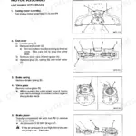
| Undercarriage Disassembly and Assembly | 134-286 | Track Frame, Recoil Spring, Front Idler, Track Roller, Carrier Roller, Track |
| Undercarriage Maintenance Standard | 287-306 | Track Frame, Recoil Spring, Idler, Track Roller, Carrier Roller, Track |
| Hydraulic System | 307-376 | Structure and Function, Testing and Adjusting, Disassembly and Assembly, Maintenance Standard, Hydraulic Pump, Blade Lift and Tilt Control Valve, Ripper Control Valve, Hydraulic Cylinder |
| Work Equipment | 377-406 | Structure and Function, Disassembly and Assembly, Maintenance Standard |
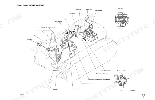
| Electric and Electronic System | 407-409 | Electrical Wiring Diagram, Electrical Circuit Diagram |
Quick Reference Specifications
| Specification | Value | Page |
|---|---|---|
| Hydraulic tank oil capacity | 108 L | p. 60 |
| Torqflow pump delivery | 73.7 l/min (at 1850 rpm) | p. 100 |
| Torqflow pump setting pressure | 20 kg/cm² | p. 100 |
| Transmission filter cracking pressure | 1.0 kg/cm² | p. 101 |
| Steering relief valve set pressure | 20 kg/cm² | p. 103 |
| Oil cooler by-pass valve set pressure | 12 kg/cm² | p. 103 |
| Steering strainer spring free length | 38 mm | p. 125 |
| Engine Oil Pan Capacity (Specified) | 30L | p. 16 |
| Engine Oil Pan Capacity (Refill) | 26L | p. 16 |
| Steering Clutch Case Oil Capacity (Specified) | 70L | p. 16 |
| Transmission Case Oil Capacity (Specified) | 52L | p. 16 |
| Cooling System Water Capacity (Specified) | 63L | p. 16 |
Komatsu D68E-1, D68P-1 Common Problems This Manual Covers
Komatsu D68E-1 torque converter oil temperature climbs high, gauge needle sitting past the green range
Check oil quantity in the transmission case and steering case first, following page 141. Verify high idle at 2,050 to 2,150 rpm and low idle at 600 to 630 rpm per page 30. Measure torque converter inlet and outlet pressure and transmission modulating relief pressure. If actual temperature is proper, suspect the gauge itself. Park on level ground, apply brakes, and release remaining oil pressure before removing any plug (page 139).
Manual Section: Power Train Troubleshooting p. 141Machine does not move off in any speed position, transmission modulating relief pressure will not rise
Check transmission and steering case oil quantity, transmission control valve spool travel, the universal joint, and whether the steering brake is locked (page 142). Measure TORQFLOW transmission setting oil pressure at high idle with oil at 40 to 60°C against 21 +3/-1 kg/cm² on page 132. With the machine on level ground and brakes applied, release remaining oil pressure before removing the pressure take-out plug (page 139).
Manual Section: Power Train Troubleshooting p. 142Drawbar pull is weak and travel speed stays low, normal power cannot be obtained
Check transmission and steering case oil level, look for leaks from piping and between case and valve, confirm the steering brake is not locked, and verify track tension, following page 144. Measure torque converter stall speed and transmission reducing valve pressure. Pull the torque converter drain plug and strainer and inspect for aluminum or steel particles. Release remaining oil pressure before removing any plug (page 139).
Manual Section: Power Train Troubleshooting p. 144Steering brake does not work and the machine will not turn on that side
Measure steering brake oil pressure with oil at 40 to 60°C against 16.7 ± 1.7 kg/cm² at both high and low idle, following page 132. Check steering setting oil pressure at high idle against 20 +4/-0 kg/cm². Keep in mind the note on page 149: if the brakes do not work, the machine will not turn. Release remaining oil pressure before removing a plug or cap (page 139).
Manual Section: Power Train Troubleshooting p. 1496D125 engine compression pressure reads low on the compression gauge, below the standard value
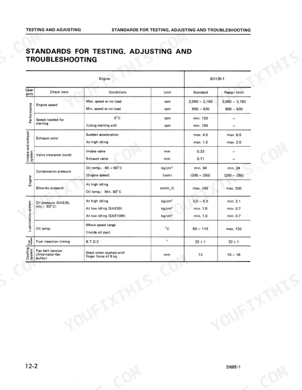
Adjust valve clearance first: cold intake 0.33 mm, exhaust 0.71 mm, locknut 6.7 ± 0.7 kgm (page 31). Warm oil to 40 to 60°C, set the fuel control lever to NO INJECTION so the engine cannot start, and crank. Compare against 34 kg/cm² minimum, repair limit 24 kg/cm², at 200 to 250 rpm (page 30). Keep clear of the exhaust manifold, muffler and rotating parts while measuring (page 32).
Manual Section: Engine Troubleshooting p. 32Fuel injection timing off after the fuel injection pump is removed, repaired or reinstalled
Set No.1 cylinder to top dead center, back the crankshaft 30 to 40 degrees, then turn it forward to align the injection line with the pointer and check pump line a against coupling line b (page 33). Torque the coupling nut to 6.2 ± 0.2 kgm. For a repaired pump, use the delivery check method on page 34. Target 22 ± 1° B.T.D.C.
Manual Section: Engine Troubleshooting p. 33Frequently Asked Questions
What is the standard tightening torque for the cylinder head mounting bolts on the Komatsu D68E-1?
The cylinder head mounting bolts must be tightened in three steps. The first step is 10 ± 1 kgm, the second step is 14 ± 0.5 kgm, and the third step is to turn the bolt 90° ± 15° after marking the bolt and head. Additionally, the bolt (1) must be tightened to 6.7 ± 0.7 kgm. p. 49
How do you adjust the valve clearance on the Komatsu D68E-1 engine?
To adjust the valve clearance, rotate the crankshaft to align the pointer with the 1.6 TOP mark with No. 1 cylinder at compression top dead center. Use a feeler gauge (part number 795-125-1360) to set the intake valve clearance to 0.33 mm and the exhaust valve clearance to 0.71 mm. Tighten the locknut to 6.7 ± 0.7 kgm after adjustment. p. 31
What is the procedure for adjusting the fan belt tension on the D68E-1?
Check the fan belt tension by pushing it midway between the fan pulley and the alternator pulley with a force of 6 kg. The belt should deflect between 10 and 16 mm. If the deflection is outside this range, loosen the mounting bolt, nut, and adjustment plate, then use a bar to raise the alternator and adjust the tension. p. 35
What is the capacity of the hydraulic tank for the Komatsu D68E-1?
The specified capacity for the hydraulic tank is 108 liters. p. 16
How do you adjust the steering lever travel on the D68E-1?
Adjust the stopper bolt (1) so the distance from the center of the steering lever knob to the dashboard is 115 mm. Then, tighten the turnbuckle (3) so the standard lever travel is 198 to 208 mm. Finally, adjust nut (4) so the clearance A is 1 mm. p. 137
Will this Komatsu D68E-1 Shop Manual download right away?
Straight to your device: 409 pages of searchable Shop Manual, downloadable the moment payment goes through.
Can I print this Komatsu D68E-1 manual?
Yes. Printing works from any reader and any printer, for your own shop use.