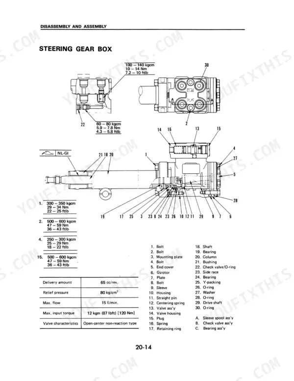
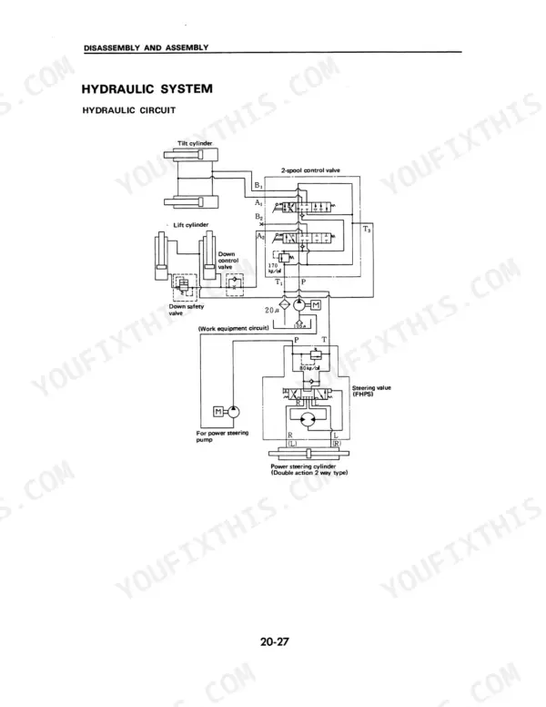
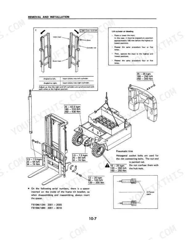
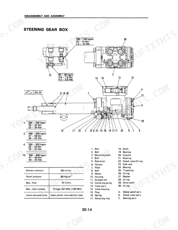
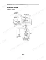
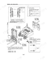
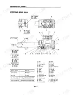
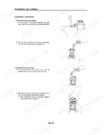
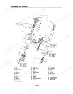
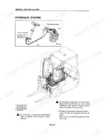
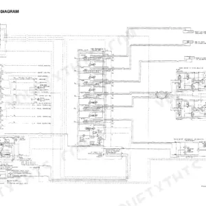
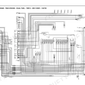
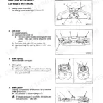
Torque values, relief pressure and the steering gear box rebuild order are settled in SM018, a 58-page Komatsu service manual for the FB10M-2 to FB18M-2 forklift truck series, four variants. Hydraulic circuit diagrams in this Komatsu FB15M-2 service manual PDF show the lift, tilt and power steering cylinder circuits, and a wiring diagram maps the electrical side. Exploded views break down the steering gear box, girotor, relief valve and control valve; mast work covers roller selection, shim adjustment and lift chain elongation. Transfer gear backlash is covered as well. Check hydraulic pump relief at a minimum of 140 kg/cm² (137 bar, 1990 psi), then torque the mast mounting bolts to 25 to 43.5 kgm (180 to 310 lbft). When your job is setting brake pad to disc clearance or bleeding air from the lift cylinder, the procedure is written out in full. Bookmarked by chapter and text-searchable, the pages print cleanly when you want a working copy beside the truck.
What's Inside This Manual
| System | Pages | Key Topics |
|---|
| General Locations | 6 | |
| Removal and Installation | 7 | Steering Gear Box |
| Weight Table | 8 | Battery Assembly, Transfer, Brake Assembly, Steering Axle, Steering Gear Box, Mast |
| Mast | 9-10 | Lift Cylinder Air Bleeding |
| Power Train | 11-12 | Anti-Vibration Rubber, Hydraulic Pump, P.S Pump, Drain Plug, Oldham Coupling |
| Brake System | 13-14 | Procedure for Adjusting Clearance Between Brake Pad and Disc, Brake Pad |
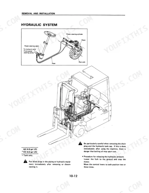
| Hydraulic System Overview and Maintenance | 15-16 | Hydraulic System Diagram, Pressure Release Procedure, Hydraulic Pump Inspection, PS Cylinder Air Bleeding |
| Brake System Removal and Adjustment | 17-19 | Accelerator Pedal Adjustment, Brake Pedal Adjustment, Parking Brake Adjustment, Brake Switch |
| Transfer Disassembly and Assembly | 20-25 | Transfer Gear Specifications, Disassembly Procedure, Assembly Procedure, Gear Backlash |
| Rear Axle and Steering Cylinder | 26-29 | Steering Axle Assembly, Power Steering Cylinder, Steering Chain Tension, PS Pump Inspection |
| Brake System Disassembly and Inspection | 30-31 | Brake System Components, Brake Pad Replacement, Inspection Data, Clearance Specifications |
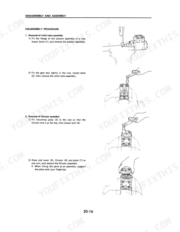
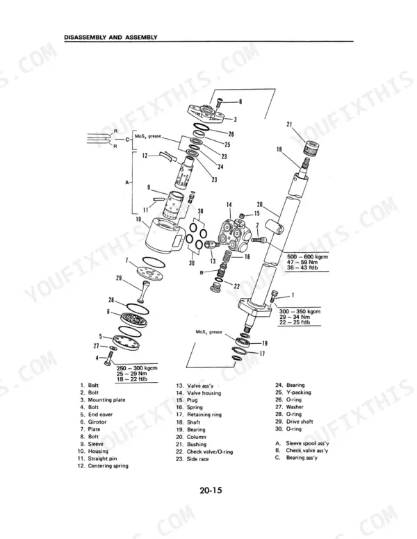
| Steering Gear Box Disassembly and Assembly | 32-44 | Steering Gear Box Components, Relief Valve Assembly, Girotor Assembly, Control Valve Assembly |
| Hydraulic Cylinder Maintenance | 45-53 | Hydraulic Circuit Diagram, Lift Cylinder, Tilt Cylinder, Power Steering Cylinder, Inspection Data |
| Mast Disassembly and Inspection | 54-58 | Mast Assembly, Roller Selection, Shim Adjustment, Lift Chain Elongation, Circuit Diagram |
Quick Reference Specifications
| Specification | Value | Page |
|---|
| Pneumatic tires rim connecting bolts torque | 16 - 25 kgm (120 - 180 lbft, 160 - 250 Nm) | p. 10 |
| Mast mounting bolt torque | 25 - 43.5 kgm (180 - 310 lbft, 250 - 430 Nm) | p. 10 |
| Drive motor bolt torque | 8 - 9 kgm (60 - 70 lbft, 80 - 90 Nm) | p. 14 |
| Hydraulic pump relief pressure | Min. 140 kg/cm² (137 bar, 1990 psi) | p. 16 |
| Delivery amount | 65 cc/rev. | p. 32 |
| Bolts (4) tightening torque | 25 - 29 Nm | p. 43 |
| Bolt (2) tightening torque | 49 - 59 Nm | p. 43 |
| Control valve assembly bolt torque | 46 Nm (34 lbft, 4.7 kgm) | p. 52 |
| Hydraulic system oil capacity | 18L | p. 11 |
| Hydraulic system tank only oil capacity | 15L | p. 11 |
| Brake system fluid capacity | 0.15L | p. 13 |
| Hydraulic system max pressure | 170 bar | p. 3 |