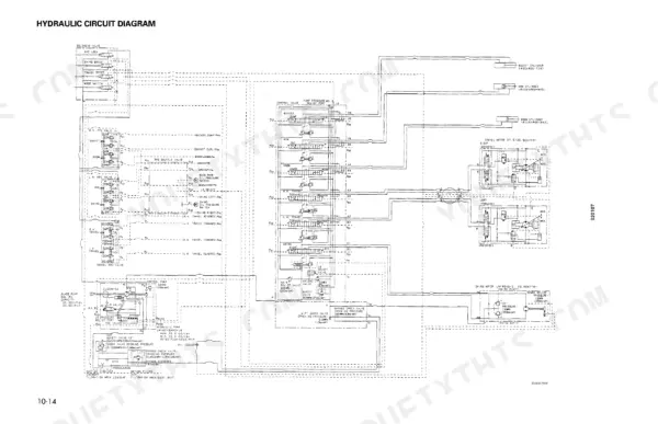
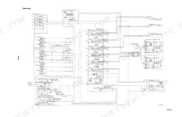
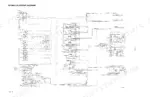
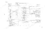
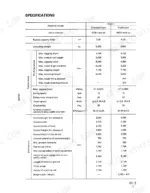
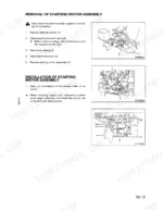
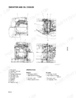
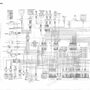
Issued by Komatsu under document number SEBM004101, this 502-page shop manual is the factory book for the PC60-7 hydraulic excavator, now offered as a Komatsu PC60-7 service manual PDF. Hydraulic circuit diagrams and piping drawings show how oil is routed through the control valve, and separate wiring diagrams lay out the machine's electrical circuits. Its five sections follow Komatsu's own order: General, Structure and Function, Testing and Adjusting, Disassembly and Assembly, and Maintenance Standard, which closes with wear limits for the swing machinery, track frame and track rollers. Fill the hydraulic tank to its 67 L oil amount within a 92 L tank capacity, then hold boom cylinder piston rod and bushing clearance at 0.085-0.326 mm. Chasing a fault? Your diagnosis runs on the troubleshooting charts and the Table of Judgement Standard Value. Bookmarks and a searchable text layer take you straight to the Special Tool List, so you can confirm what to order before disassembly begins.
What's Inside This Komatsu PC60-7 Manual
| System | Pages | Key Topics |
|---|---|---|
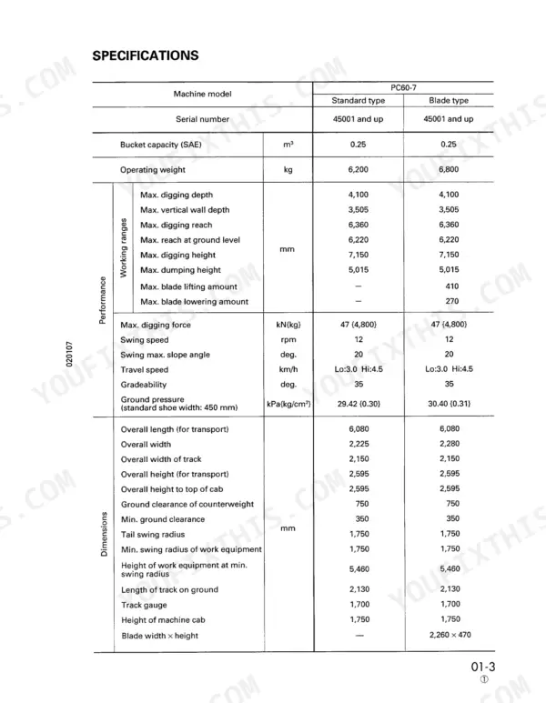
| General | 21-28 | General Assembly Drawing, Specifications, Weight Table |
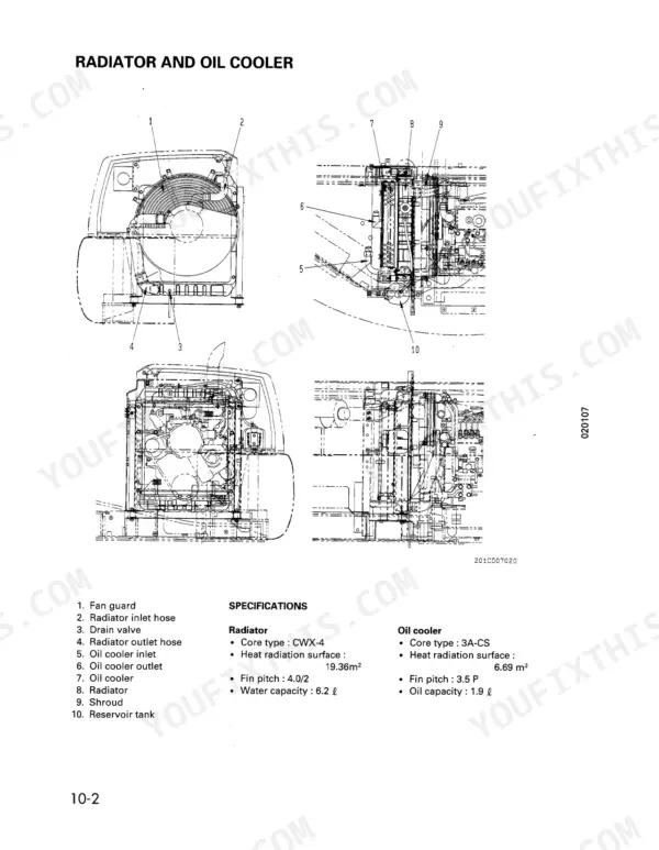
| Structure and Function | 29-177 | Hydraulic Piping Drawing, Hydraulic Circuit Diagram, Control Valve |
| Testing and Adjusting | 178-348 | Table of Judgement Standard Value, Troubleshooting |
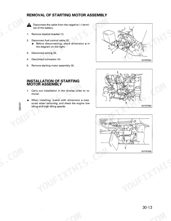
| Disassembly and Assembly | 349-466 | Method of Using Manual, Precautions When Carrying Out Operation, Special Tool List |
| Maintenance Standard | 467-502 | Swing Machinery, Track Frame, Track Roller |
Quick Reference Specifications
| Specification | Value | Page |
|---|---|---|
| Tank capacity | 92 L | p. 44 |
| Oil amount | 67 L | p. 44 |
| Boom cylinder piston rod and bushing clearance | 0.085-0.326 mm | p. 501 |
| Arm cylinder piston rod and bushing clearance | 0.024-0.227 mm | p. 501 |
| Control pump relief valve set pressure | 2.94 MPa (30 kg/cm²) | p. 187 |
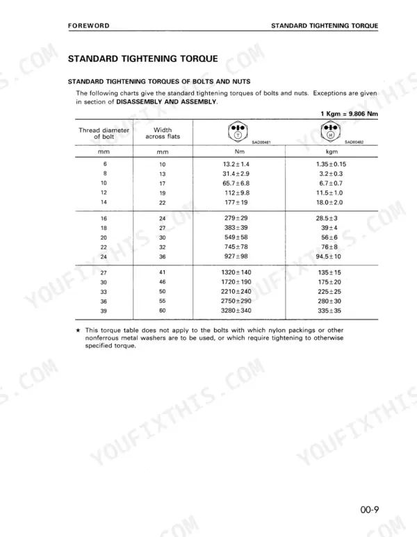
| PC valve lock nut torque | 100.5 ± 12.3 Nm (10.25 ± 1.25 kgm) | p. 206 |
| LS valve lock nut torque | 56.4 ± 7.4 Nm (5.75 ± 0.75 kgm) | p. 208 |
| Main relief valve adjustment amount for one turn | 12.5 MPa (128 kg/cm2) | p. 206 |
| Resistance value between (1) and (2) of the pressure detecting switch | Max. 1 Ω | p. 343 |
| Voltage between (2) and (3) of the motor | 20 - 30 V | p. 343 |
| Control Valve torque | 110.3 ± 12.3 Nm (11.25 ± 1.25 kgm) | p. 482 |
| Lift check valve spring torque | 44.1 ± 4.9 Nm (4.5 ± 0.5 kgm) | p. 483 |
Komatsu PC60-7 Common Problems This Manual Covers
Komatsu PC60-7 work equipment does not move with PPC hydraulic pressure lock lever set to DRIVE
Check connector engagement first, then confirm fuse 2 is intact. With the starting switch ON and lock lever at DRIVE, measure V1(2) to chassis following page 264; it must read 1V or lower. Measure V1(1) to chassis for 20 to 30 V. Replace the PPC hydraulic pressure lock solenoid, lock switch, or broken wire harness as the chart directs.
Manual Section: Engine Throttle Controller System (E Mode) and Engine (S Mode) p. 264Machine does not swing when the swing lever is operated with swing lock switch OFF
Park the machine on level ground before testing, as page 178 requires. Set both the swing lock switch and swing prolix switch OFF and confirm fuse 2 is intact. With the starting switch ON, measure C1(1) to (2) following page 266 for 20 to 30 V. Disconnect V4 with the starting switch OFF and check (1) to (2) for 20 to 60 Ω, and (2) to chassis at 1 MΩ or higher.
Manual Section: Engine Throttle Controller System (E Mode) and Engine (S Mode) p. 266Swing brake does not work with swing lever returned to NEUTRAL and starting switch ON
Check connector engagement, then with the starting switch ON and lever at NEUTRAL, measure V4(1) to chassis following page 269; it should read 1V or lower. With the starting switch OFF and V4 disconnected, verify (2) to chassis at 1 MΩ or higher. Test the switch terminals alone: 1 Ω or lower when ON, 1 MΩ or higher when OFF.
Manual Section: Engine Throttle Controller System (E Mode) and Engine (S Mode) p. 269Travel speed cannot be switched to Hi with travel speed select switch moved to Hi side
Confirm fuse 2 is intact. Turn the starting switch ON, move the switch to Hi, and measure V5(2) to chassis following page 271 for 1V or lower. Check V5(1) to chassis for 20 to 30 V. Test the travel speed select switch alone: 1 Ω or lower at Hi, 1 MΩ or higher at Lo. Replace the defective switch, solenoid, or wire harness.
Manual Section: Engine Throttle Controller System (E Mode) and Engine (S Mode) p. 271Engine does not start and starter does not work when starting switch is turned to START
Check battery voltage and specific gravity first following page 273: 24V or higher and 1.26 or more. Turn the starting switch to START and listen for the starter pinion engaging. Listen for the battery relay sound when the switch goes OFF, then measure terminal B of the starting switch for 20 to 29 V before condemning the starter circuit.
Manual Section: Engine Throttle Controller System (E Mode) and Engine (S Mode) p. 273Engine does not start because engine stop solenoid does not work with starting switch ON
With the starting switch ON, measure the engine stop solenoid terminal to chassis following page 275 for 20 to 30 V. Turn the switch OFF, disconnect the solenoid terminal, and check resistance to chassis at 1 Ω or lower. Check ACC of the starting switch for 20 to 30 V. Replace the solenoid, wire harness, or starting switch accordingly.
Manual Section: Engine Throttle Controller System (E Mode) and Engine (S Mode) p. 275Frequently Asked Questions
How do you reset the auto-greasing controller error code?
To reset an 'abnormal pressure' error, press the [RESET/ESC] button once. To reset an 'abnormal setting' error, press and hold the [RESET/ESC] switch for more than 5 seconds until the display shows '0' for about 2 seconds and the small dot flashes. p. 224
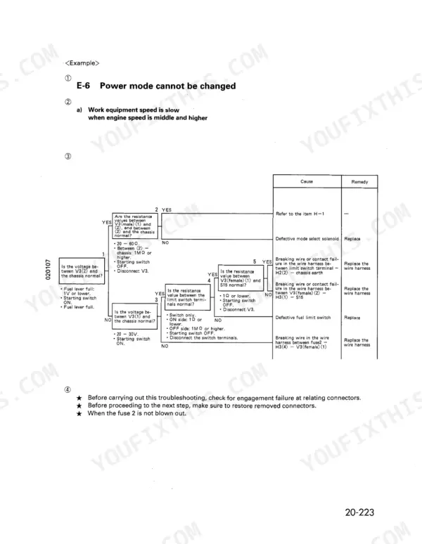
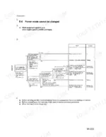
Why can’t the PC60-7 power mode be changed?
If the power mode cannot be changed, it may be due to a defective mode select solenoid, a broken wire in the harness between the limit switch terminal and chassis earth, or a defective fuel limit switch. Refer to page 272 for the troubleshooting flow chart and related electrical circuit diagram. p. 272
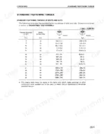
What is the standard tightening torque for the cylinder head mounting bolts on the Komatsu PC60-7?
The cylinder head mounting bolts must be tightened in three passes. The first pass is 68.6 ± 9.8 Nm (7 ± 1 kgm), the second pass is 107.8 ± 4.9 Nm (11 ± 0.5 kgm), and the third pass is 90° + 10° using an angle tightening wrench. p. 372
What is the standard valve clearance for the engine on the Komatsu PC60-7?
The standard valve clearance for both the intake and exhaust valves at normal temperature is 0.35 mm for intake and 0.50 mm for exhaust. p. 179
What is the specified hydraulic tank capacity for the Komatsu PC60-7?
The hydraulic tank has a total capacity of 92 liters, with a refill capacity of 67 liters. p. 44
Do I get instant access to this Komatsu PC60-7 Service Manual?
Delivery is instant: a 502-page searchable PDF is yours the second checkout clears. Laptop, tablet, or phone, all fine.
Can I print just the pages I need from this Komatsu PC60-7 manual?
Yes. Print individual pages or full chapters for your own shop use, on letter or A4 paper.