
Shop manual SEBM000906 applies to a single machine, the PC50UU-2 hydraulic excavator, and this 828-page Komatsu PC50UU-2 service manual PDF reproduces it, so you know it fits the unit in your yard before a cover comes off. Testing and Adjusting fills over a third of the book, and its judgement standard value tables give you the factory figure to hold each pressure and electrical reading against. Disassembly and Assembly runs about as long, covering the fuel injection pump, cylinder head, swing machinery and swing motor, while hydraulic and electric circuit diagrams trace the lines from main pump to spool control valve. Fill the engine oil pan to 9.1 L (8.5 L on a refill) and run standard 10 mm bolts to 66 ± 7 Nm. Some days it's you, the machine, and nobody to ask. Bookmarked by section and text-searchable, the PDF sits on the laptop in your service truck, so it goes wherever the excavator does.
What's Inside This Komatsu PC50UU-2 Manual
| System | Pages | Key Topics |
|---|---|---|
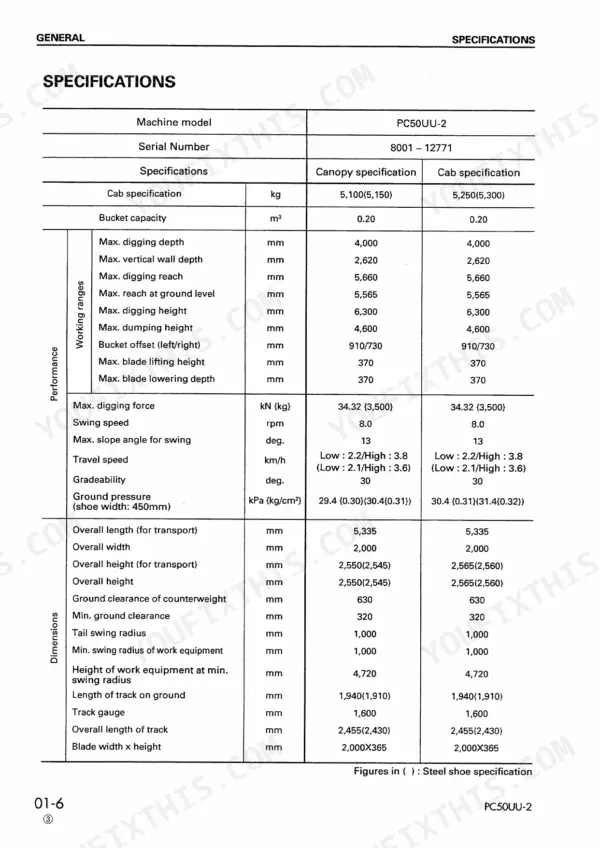
| General | 27-44 | General Assembly Drawing, Specifications, Weight Table |
| Structure and Function | 45-170 | Power Train System, Swing Machinery, Track Frame, Hydraulic Piping Diagram, Main Pump, Spool Control Valve, Swing Motor |
| Testing and Adjusting | 171-463 | Table of Judgement Standard Value, Standard Value Table for Electrical Parts, Tools for Testing, Adjusting, And Troubleshooting |
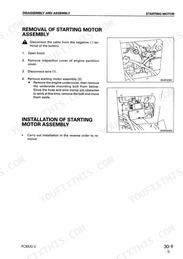
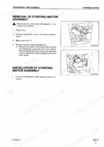
| Disassembly and Assembly | 464-759 | Starting Motor, Alternator, Fuel Injection Pump, Water Pump, Cylinder Head, Swing Machinery and Swing Motor |
| Maintenance Standard | 760-819 | Swing Machinery, Idler, Track Roller |
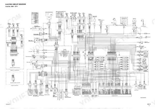
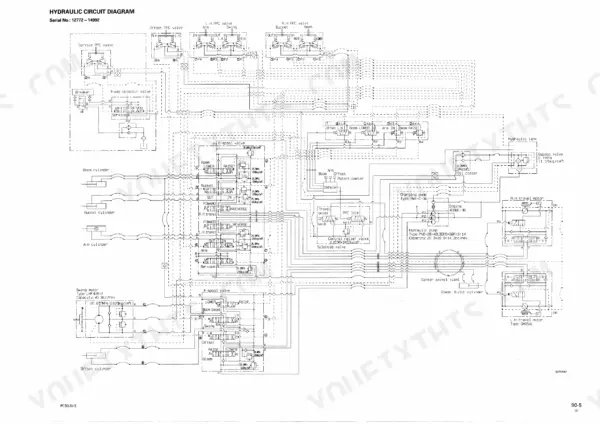
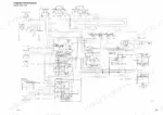
| Others | 820-828 | Hydraulic Circuit Diagram, Electric Circuit Diagram |
Quick Reference Specifications
| Specification | Value | Page |
|---|---|---|
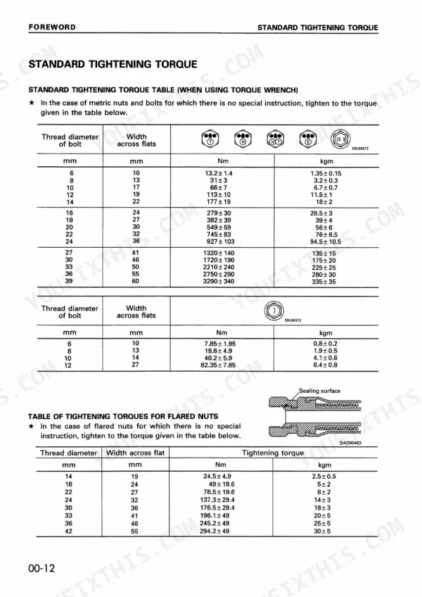
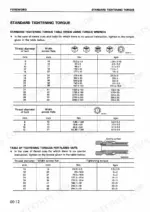
| Standard tightening torque for metric bolts (6mm) | 13.2 ± 1.4 Nm | p. 16 |
| Standard tightening torque for metric bolts (8mm) | 31 ± 3 Nm | p. 16 |
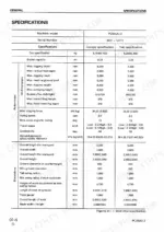
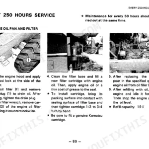
| Engine oil pan capacity (Specified) | 9.1 L | p. 42 |
| Engine oil pan capacity (Refill) | 8.5 L | p. 42 |
| Pressure valve relief cracking pressure | 38.3 ± 14.7 kPa | p. 62 |
| Pressure valve suction cracking pressure | 0 - 4.5 kPa | p. 62 |
| Oil temperature when measuring | 45-55°C | p. 221 |
| Hydraulic hose and tube cork dimensions (Nominal 06) | 6 mm (D), 5 mm (d), 8 mm (L) | p. 467 |
| Hydraulic hose and tube cork dimensions (Nominal 10) | 10 mm (D), 8.5 mm (d), 12 mm (L) | p. 467 |
| PPC Valve Centering spring (for P3, P4) installed load | 55.9 N (5.7 kg) | p. 809 |
| PPC Valve Centering spring (for P1, P2) installed load | 29.4 N (3.0 kg) | p. 485 |
Komatsu PC50UU-2 Common Problems This Manual Covers
Komatsu PC50UU-2 track shoe tension too tight or too slack between idler and carrier roller
Measure slack following page 206: at low idling, roll forward one track length, stop slowly, and lay a straight-edge over the idler and carrier roller. If tight, loosen the valve to bleed grease, but never more than 1 turn, since high-pressure grease may spout out. If slack, pump G2-LI grease through the grease fitting, then retest.
Manual Section: Testing and adjusting track shoe tension p. 206Boom, arm and bucket work equipment lacking power with main relief pressure below standard
Test main relief pressure following page 208. First lower the work equipment, stop the engine, loosen the oil filler cap slowly to release tank pressure, and put the safety lock lever in LOCK. Install gauge C1 at the pick-up plug, bring oil to 45 to 55°C, hold each cylinder at stroke end at full throttle, and check for 20.58 MPa (210 kg/cm²) per page 421.
Manual Section: Testing and adjusting hydraulic pressure p. 208Swing motor relief pressure reading lower than main relief pressure on the gauge
Check the reading against the note on page 208: the swing motor safety valve is set lower than the main relief valve, so a relieved swing shows the safety valve pressure. Adjust only the swing motor safety valve here; page 211 warns not to adjust its set pressure for any other part. Torque the locknut to 34.3 ± 5 Nm, or 105.45 ± 12.25 Nm on serial 14993 and up (page 212).
Manual Section: Testing and adjusting hydraulic pressure p. 211Electronic system caution lamp flashing with error code 61 and all actuators stopped
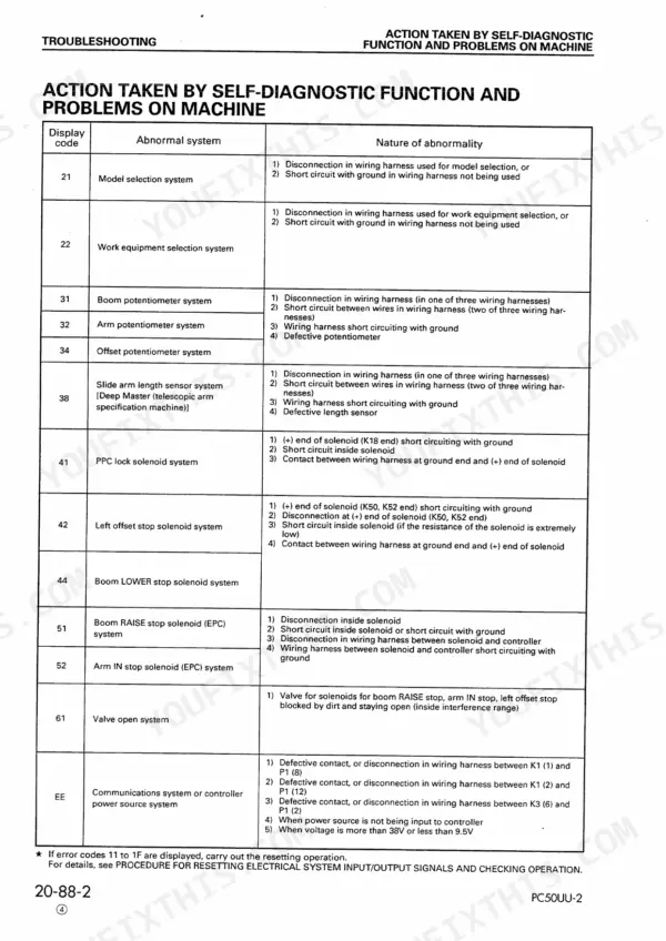
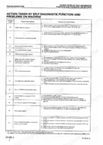
Verify code 61 on the depth display as shown on page 148, then set the canceling switch under the operator's seat to ON only to move the machine to a safe place (page 149). If cancel will not work, suspect the EPC solenoid valves or electrical system. Test boom potentiometer M11 resistance between pins (1) and (3) at 4 to 6 kΩ, starting switch OFF, per page 191.
Manual Section: Troubleshooting of controller electrical system (E mode) p. 148Charge caution lamp staying lit with alternator output low at half throttle
Measure voltage between alternator terminal L and chassis with the engine running at 1/2 throttle or above, following page 194, and expect 13.5 to 14.5 V. An old battery or a cold start can delay the voltage rise, so recheck after the machine runs a while. Before going deeper, verify all related connectors are fully inserted, as page 460 instructs.
Manual Section: Standard value table for electrical parts p. 194Engine oil pressure caution lamp lighting with engine running while oil pressure is normal
Check that all related connectors are properly inserted per page 455, then confirm real pressure: remove the oil pressure switch, fit gauge kit C1 and gauge C2, and measure at low and high idling following page 197. Test sensor T9 terminal to chassis on page 194; above 0.7 kg/cm² it should read min. 1 MΩ.
Manual Section: Troubleshooting of machine monitor system (M mode) p. 455Frequently Asked Questions
How do I reset the Komatsu PC50UU-2 boom/stick/bucket circuit after an automatic stop?
If the machine stops due to the interference prevention system, you can resume work by moving the bucket to the outside of the stop zone using the control system that has not been stopped. If the emergency stop function is activated, you can move the machine to a safe place by setting the canceling switch located under the operator's seat to ON, as described on page 149. p. 148
What does error code 61 mean on a Komatsu PC50UU-2?
Error code 61 indicates that a solenoid valve spool in systems (4), (5), or (6) did not close. This results in the PPC basic pressure being cut off, making movement of all work equipment and swing impossible. If this occurs, the system returns to normal mode only after the location of the failure is reset. p. 328
How do I troubleshoot weak or slow boom, arm, or bucket operation?
First, ensure the hydraulic drift of the work equipment is normal and the swing is functioning correctly. If the speed is slow, check the output pressure of the PPC valve; for the boom, arm, and bucket, the standard pressure is 2.94 ± 0.1 MPa (30 ± 1 kg/cm²). If the pressure is low, check for defective operation of the control valve spool or PPC valve. p. 433
What is the tightening torque for the cylinder head mounting bolts on the Komatsu PC50UU-2?
The cylinder head mounting bolts must be tightened in three stages: first to 29.4 ± 4.9 Nm (3.0 ± 0.5 kgm), second to 58.8 ± 4.9 Nm (6.0 ± 0.5 kgm), and finally to 78.5 ± 4.9 Nm (8.0 ± 0.5 kgm). p. 485
What is the standard valve clearance for the engine on the Komatsu PC50UU-2?
The standard valve clearance for both intake and exhaust valves at normal temperature is 0.2 mm. p. 172
How will I receive this Komatsu PC50UU-2 Service Manual?
Straight to your device: 828 pages of searchable Service Manual, downloadable the moment payment goes through.
Am I free to print this Komatsu PC50UU-2 Service Manual?
Yes. Print a single page or a chapter for your own shop use, on letter or A4.



Reviews
There are no reviews yet.