
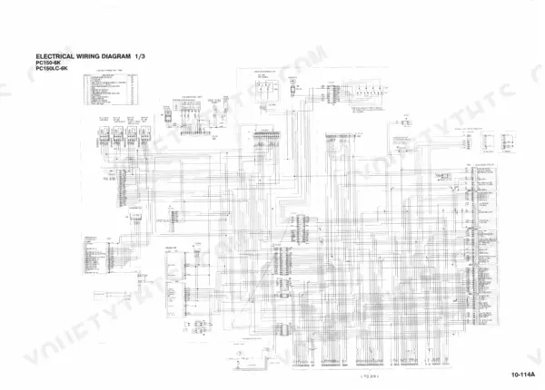
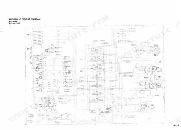
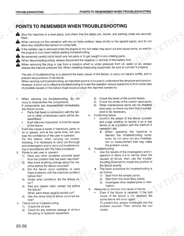
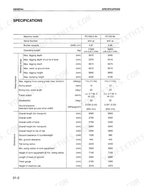
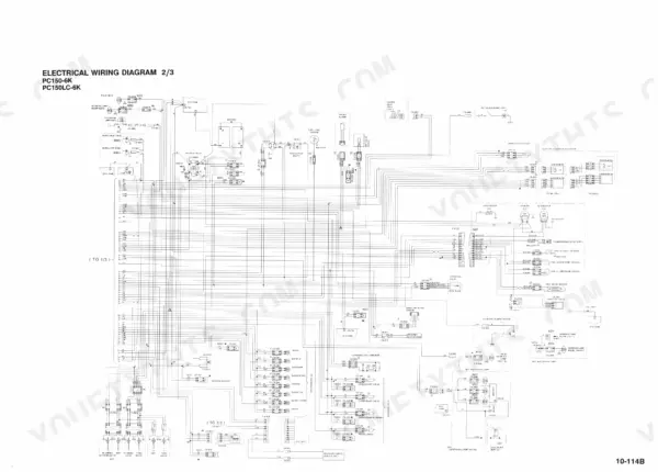


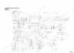
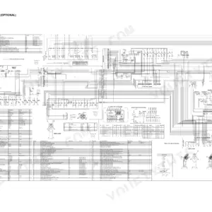
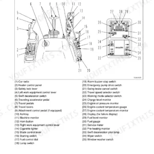
Travel deviation, sluggish boom speed or a service code can stall a crew for a day while someone hunts for the cause, and the Komatsu PC150-6K, PC150LC-6K shop manual PDF (OEM ID CEBM001601) answers it with 617 pages of factory data for both hydraulic excavators. Troubleshooting claims the largest share of the book, split into E, C, F and H modes so a fault traces to the governor and pump controller, an input pressure switch, or the hydraulic circuit. Hydraulic schematics follow CLSS flow from pump to control valve, wiring diagrams map the controller harnesses, and the disassembly chapter takes the final drive and swing machinery apart and back together. Set main relief at 31.4 to 34.8 MPa; with the engine above half throttle, your alternator should read 27.5 to 29.6 V. A guessed pressure switch costs the part, the freight and a second teardown. The bookmarked, searchable PDF lets you find the failed component before ordering anything.
What's Inside This Komatsu PC150-6K, PC150LC-6K Manual
| System | Pages | Key Topics |
|---|---|---|
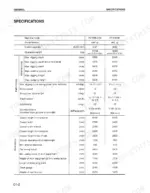
| General | 10-20 | Specifications, Weight Table, Fuel, Coolant and Lubricants |
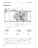
| Structure and Function | 21-182 | Engine Related Parts, Hydraulic Pump, Control Valve, Clss |
| Testing and Adjusting Procedures | 183-230 | Standard Values, Belt Tension, Engine Speed Sensor, Hydraulic Pressure Testing, Oil Leakage Measurement, Air Bleeding |
| Troubleshooting Introduction and Procedures | 231-276 | Troubleshooting Sequence, Electrical System Precautions, Service Code Table, Communication Abnormality System, Monitor Panel Display |
| Governor and Pump Controller Troubleshooting (E and C Modes) | 277-363 | E-Mode Troubleshooting, Engine Starting Issues, Engine Speed Irregularities, C-Mode Troubleshooting, Pump TVC Solenoid System |
| Input Signal System Troubleshooting (F Mode) | 364-377 | F-Mode Troubleshooting, Bit Pattern Analysis, Swing Oil Pressure Switch, Travel Oil Pressure Switch, Boom/Arm/Bucket Pressure Switches |
| Hydraulic and Mechanical System Troubleshooting (H Mode) | 378-414 | H-Mode Troubleshooting, Work Equipment Speed Issues, Travel Deviation, Swing System Issues, Machine Monitor System Troubleshooting |
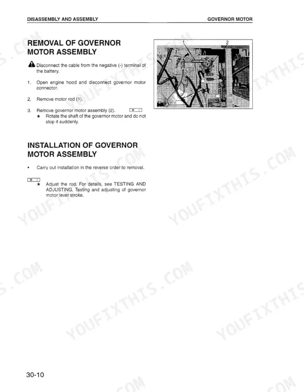
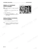
| Disassembly and Assembly | 446-578 | Special Tool List, Final Drive Assembly, Swing Machinery Assembly |
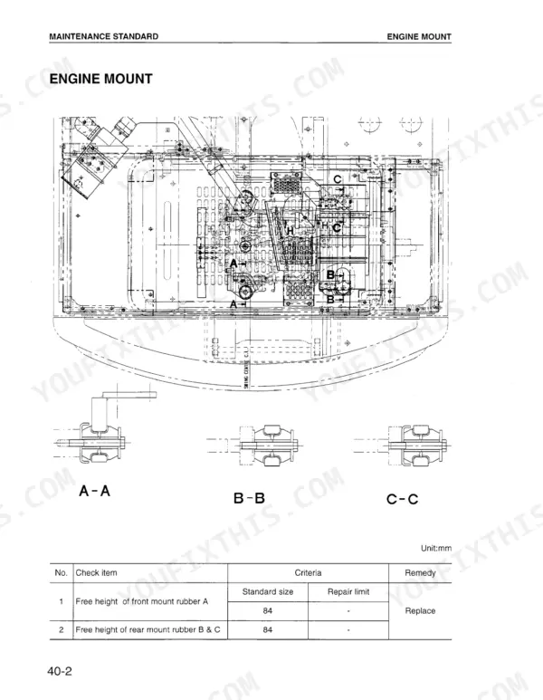
| Maintenance Standard | 579-617 | Idler, Track Roller, Control Valve |
Quick Reference Specifications
| Specification | Value | Page |
|---|---|---|
| Additional filter for breaker rated pressure | 6.86 MPa | p. 126 |
| Additional filter for breaker relief valve cracking pressure | 0.34 ± 0.049 MPa | p. 126 |
| Battery voltage (engine stopped) | 20 - 30 V | p. 241 |
| Alternator voltage (engine running at over half throttle) | 27.5 - 29.6 V | p. 241 |
| Main pump relief pressure | 31.4 - 34.8 MPa (320 - 355 kg/cm²) | p. 383 |
| LS control EPC valve output pressure | 0.2 ± 0.2 MPa (2 ± 2 kg/cm²) | p. 383 |
| Tightening torque for flared nuts (14 mm thread diameter) | 2.5 ± 0.5 kgm (24.5 ± 4.9 Nm) | p. 449 |
| Tightening torque for flared nuts (18 mm thread diameter) | 5 ± 2 kgm (49 ± 19.6 Nm) | p. 449 |
| Swing circle mounting bolt tightening torque | 490-608 Nm | p. 583 |
| Main Relief Valve Tightening Torque | 98.1 ± 9.8 Nm | p. 489 |
| Track Shoe Tension Clearance | 303 ± 20 mm | p. 207 |
Komatsu PC150-6K, PC150LC-6K Common Problems This Manual Covers
Komatsu PC150-6K hydraulic work equipment weak and slow across all functions with low main pump relief pressure
Measure main pump relief pressure following page 383 and compare it against 31.4 to 34.8 MPa (320 to 355 kg/cm²). While the circuit is at relief, check engine speed against 2,100 ± 100 rpm on page 185. Test the LS bypass solenoid valve output on page 383 against 2.9 ± 0.5 MPa before you condemn the pump.
Manual Section: Hydraulic, Mechanical System (H Mode) p. 383Arm cylinder speed slow or arm lacks power during digging and loading work
Measure arm relief pressure following page 390 and confirm it reads 31.4 to 34.8 MPa (320 to 355 kg/cm²). On the same page, check that PPC valve output pressure is at least 2.7 MPa (28 kg/cm²). If both pass, measure arm cylinder leakage on page 391. Anything over 20 cc/min puts the problem in the cylinder.
Manual Section: Hydraulic, Mechanical System (H Mode) p. 390Boom or bucket moves slowly and lacks power during normal digging and loading cycles
Check work equipment PPC valve output pressure following page 393 against a minimum of 2.7 MPa (28 kg/cm²), then measure boom cylinder leakage against a maximum of 20 cc/min. For the bucket, run the same checks on page 392: PPC output of at least 2.7 MPa and bucket cylinder leakage of no more than 20 cc/min.
Manual Section: Hydraulic, Mechanical System (H Mode) p. 393LS-EPC solenoid output pressure out of range at low idle in every working mode
Measure LS-EPC solenoid output pressure following page 394 with the engine at low idle (approx. 1100 rpm or below). Expect approx. 2.5 MPa (approx. 26 kg/cm²) in any working mode. If the reading is off, work through the Governor, Pump Controller (C Mode) troubleshooting for the LS bypass and pressure sensor circuits before replacing hydraulic parts.
Manual Section: Hydraulic, Mechanical System (H Mode) p. 394Battery keeps going flat or alternator not charging, with low voltage at the battery terminals
Measure battery voltage with the engine stopped following page 241. It should read 20 to 30 V. Then start the engine, hold it above half throttle and check alternator voltage against 27.5 to 29.6 V. A low reading with the engine running means the fault is in the charging circuit, not the battery.
Manual Section: Troubleshooting Introduction and Procedures p. 241Track chain sagging or running too tight, track shoe tension clearance out of spec
Measure track shoe tension clearance following page 207 and adjust it until it reads 303 ± 20 mm. While you are on the undercarriage, check the shoe bolts. Retighten any loose ones following page 592 to an initial 392 ± 39.2 Nm (40 ± 4 kgm), then turn them an additional 120° ± 10°.
Manual Section: Testing and Adjusting Procedures p. 207Frequently Asked Questions
How do I reset the service code on a Komatsu PC150-6K or PC150LC-6K?
To reset the service code, turn the starting switch OFF. Then, keep the time switch at the back of the monitor panel depressed, switch the starting switch ON again, and continue to hold the time switch depressed for 5 seconds. This operation will erase all service codes stored in the internal memory. p. 415
How do I troubleshoot an engine that will not start on a PC150LC-6K?
If the starting motor does not rotate, check that fuse No. 14 is not blown. If the starting motor rotates but the engine does not start, check the fuel level and ensure there is no air in the fuel system. Refer to the troubleshooting flowcharts for E-8 (Engine does not start) on page 295 or S-2 (Engine does not start) on page 313 for detailed diagnostic steps. p. 295
What is the standard belt tension for the air conditioner compressor?
The compressor drive belt should deflect by about 15-18 mm (0.60-0.70 inch) when pressed with a force of approximately 6 kg (13 lb) at the midpoint between the fan pulley and the compressor pulley. p. 202
What is the tightening torque for the final drive mounting bolts on the Komatsu PC150-6K, PC150LC-6K?
The final drive mounting bolts should be tightened to a torque of 549 ± 59 Nm (56 ± 6 kgm). p. 458
What is the standard clearance for the swing circle bearing when mounted on the Komatsu PC150-6K, PC150LC-6K?
The standard axial clearance for the swing circle bearing when mounted on the machine is 0.5 - 1.6 mm, with a clearance limit of 3.2 mm. p. 583
Is this Komatsu PC150-6K Shop Manual a digital download?
You get a 617-page searchable PDF that downloads instantly after checkout. Open it on your laptop, tablet, or phone, and bring it right to the shop floor.
Can I print specific sections of this Komatsu PC150-6K Shop Manual?
Yes. Print a single page or a chapter for your own shop use, on letter or A4.


Reviews
There are no reviews yet.