
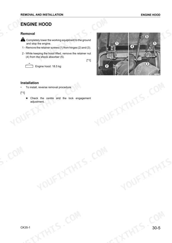
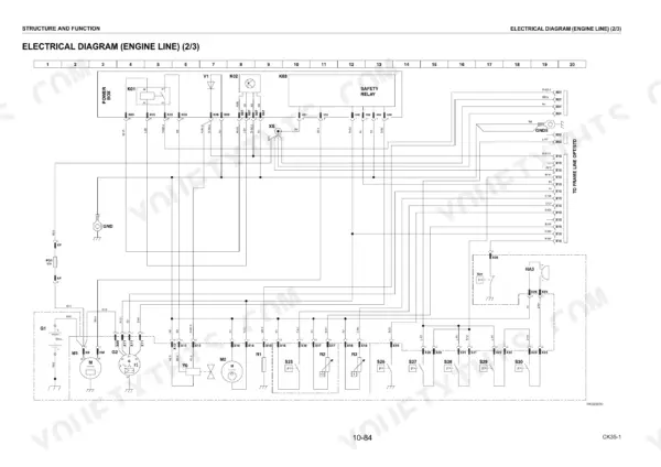
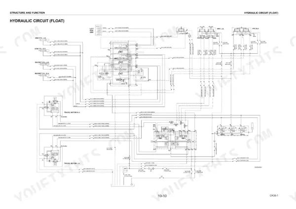
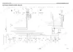
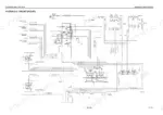
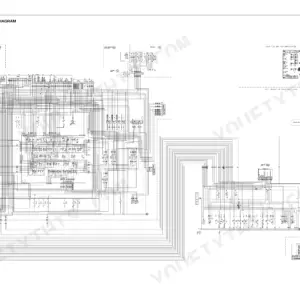
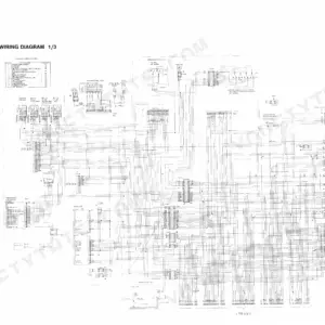
Written for the CK35-1 compact track loader, this Komatsu CK35-1 shop manual PDF (OEM ID CEBM017500) runs 304 pages across structure and function, testing and adjusting, removal and installation, and maintenance standards. Hydraulic schematics trace the pump, control valve and CLSS load sensing circuit, and the wiring diagrams follow each harness to its connector, so a dead circuit or lazy lift arms become a path you can follow. Removal and installation fill roughly a third of the book, taking the cab, injection pump and final drive out and back in. Fill the hydraulic system and hydrostatic transmission with 50 L on first fill (32 L at a refill), and put 10.2 L in the engine oil pan. Every parked hour is material not moving. Bookmarks take you straight to the chapter you want, and the text layer lets you search any part name in seconds.
What's Inside This Komatsu CK35-1 Manual
| System | Pages | Key Topics |
|---|---|---|
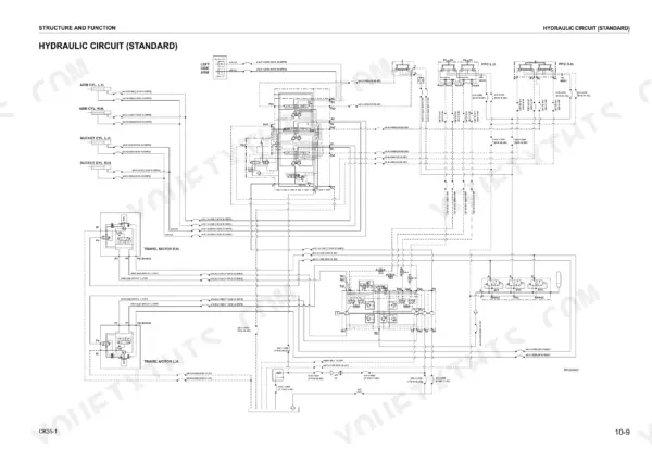
| Structure and Function | 25-132 | Hydraulic Pump, Control Valve, Clss |
| Testing and Adjusting | 133-170 | Normal or Standard Technical Data, Checking the Engine Speed, Adjustment of Valve Clearance |
| Removal and Installation | 171-268 | Cab, Injection Pump, Final Drive |
| Maintenance Standard | 269-298 | Control Valve |
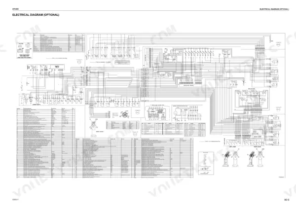
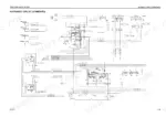
| Other | 299-304 | Electrical Diagram |
Quick Reference Specifications
| Specification | Value | Page |
|---|---|---|
| Engine oil pan capacity (1st filling) | 10.2 L | p. 15 |
| Engine oil pan capacity (Refill) | 10.2 L | p. 15 |
| Final drive oil capacity (1st filling) | 1.17 L | p. 15 |
| Final drive oil capacity (Refill) | 1.17 L | p. 15 |
| Final Drive Oil Capacity (each) | 1.3 L | p. 244 |
| General fuse | 50A | p. 109 |
| Battery | 80Ah | p. 109 |
| Working pressure of the AS valve (low idling) | 11.8±0.5 bar | p. 137 |
| Working pressure of the AS valve (2500±30 rpm) | 16.7±0.5 bar | p. 137 |
| Standard distance (gap A) | 15-20 mm | p. 140 |
| Track 320 mm weight | 180 kg | p. 235 |
| Track 450 mm weight | 241 kg | p. 235 |
Komatsu CK35-1 Common Problems This Manual Covers
Komatsu CK35-1 travel circuit HST charge valve and AS valve working pressure reading low on gauge
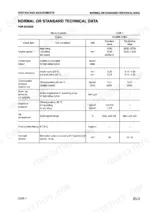
Test working pressure of the travel circuit HST charge valve and AS valve. Compare the AS valve reading against 11.8 ± 0.5 bar at low idle and 16.7 ± 0.5 bar at 2500 ± 30 rpm using the table on page 137. If readings fall outside range, calibrate the HST and AS valves before condemning the pump.
Manual Section: Testing and Adjusting p. 137PPC valve drive pressure low with levers at full stroke, work equipment and travel response slow
Measure PPC pressure with the levers held at full stroke and compare it against 16.5 ± 0.5 bar listed on page 137. If the reading is low, follow the PPC valve drive pressure regulation procedure: disassemble the valve, regulate it, then reassemble. Recheck the reading at full stroke after assembly before returning the machine to work.
Manual Section: PPC Valve Drive Pressure Regulation p. 137Machine drifts off a straight line during travel, one track running slower than the other
Check travel deviation following the Travel Deviation Checking procedure in Testing and Adjusting, then adjust until both tracks run true. If drift persists after adjustment, verify HST valve calibration and recheck AS valve working pressure against 11.8 ± 0.5 bar at low idle, listed on page 137, before tearing into the final drive.
Manual Section: Travel Deviation CheckingTrack running slack, with sag gap at the central roller outside standard distance
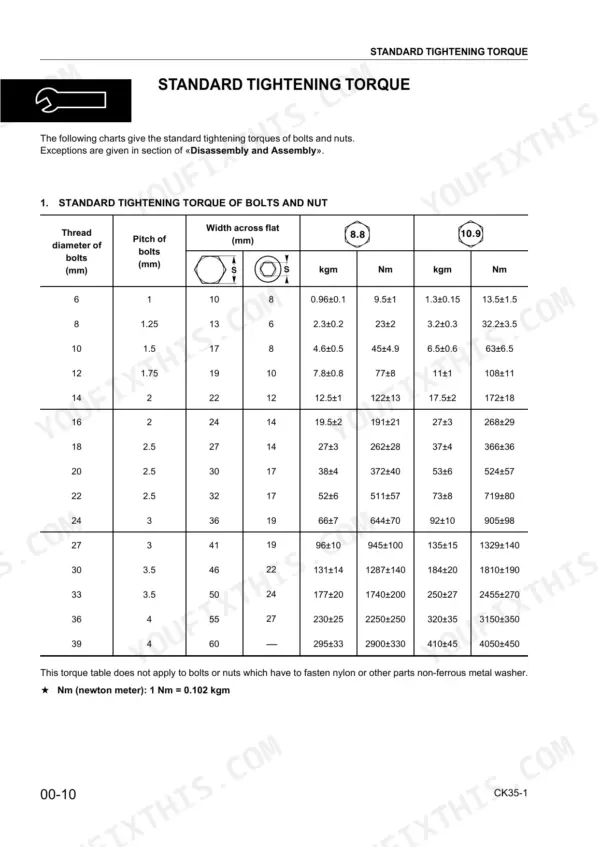
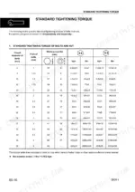
Measure gap A at the central roller and compare it against the 15 to 20 mm standard distance shown on page 140. Adjust track tension until the gap falls inside that window. While you are under there, check the track tensioner idler wheel bolts and torque them to 574 Nm per page 272.
Manual Section: Testing and Adjusting p. 140Engine fan belt running loose, with flexion measured well over the allowed range
Check fan belt tension by pressing the belt with 98 N of force and measuring flexion. Adjust the belt until flexion reads 7 to 10 mm, as listed on page 149. Recheck flexion after locking the adjustment down, and replace any belt that will not hold that range.
Manual Section: Fan Belt Tension Control p. 149Engine compression pressure reading low on one or more cylinders at the test gauge
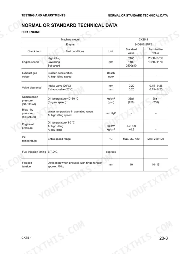
Measure compression pressure on each cylinder and compare against 35 ± 1 kg/cm² with SAE30 oil, listed on page 135. Before going deeper into the engine, check valve clearance and set intake and exhaust to 0.20 mm, working through the ignition sequence. Retest compression after adjustment to confirm the reading recovers.
Manual Section: Testing and Adjusting p. 135Frequently Asked Questions
What is the standard valve clearance for the engine on the Komatsu CK35-1?
The standard valve clearance for both the intake and exhaust valves is 0.20 mm when the engine is at 20°C. The permissible range for these clearances is 0.15 to 0.25 mm. p. 135
What is the tightening torque for the cylinder head screws on the Komatsu CK35-1?
The cylinder head screws require a two-stage tightening process. The first tightening is 49.0–58.8 Nm, and the second tightening is 103.1–112.9 Nm. p. 198
What is the hydraulic system and hydrostatic transmission capacity on the Komatsu CK35-1?
The first filling capacity for the hydraulic system and hydrostatic transmission is 50 liters, while the refill capacity is 32 liters. p. 15
What is the correct fan belt tension for the engine?
The fan belt tension should be adjusted so that the flexion is 10 mm when pressed with a force of approximately 10 kg. The permissible range for this deflection is 10–15 mm. p. 135
What is the procedure for bleeding air from the hydraulic pump?
To bleed air from the pump, loosen and remove the cap from the pump body, pour hydraulic oil through the hole until the casing is full, and replace the cap. After filling, run the engine at low idling for about 10 minutes before proceeding to bleed the rest of the circuits. p. 168
What format is this Komatsu CK35-1 manual in?
A single searchable PDF file of 304 pages, downloadable right after payment. Nothing ships, nothing waits in the mail.
Is this Komatsu CK35-1 Shop Manual printable?
Yes. Print the sections you need to take out to the shop for your own use. Standard letter or A4 paper works.


Reviews
There are no reviews yet.