
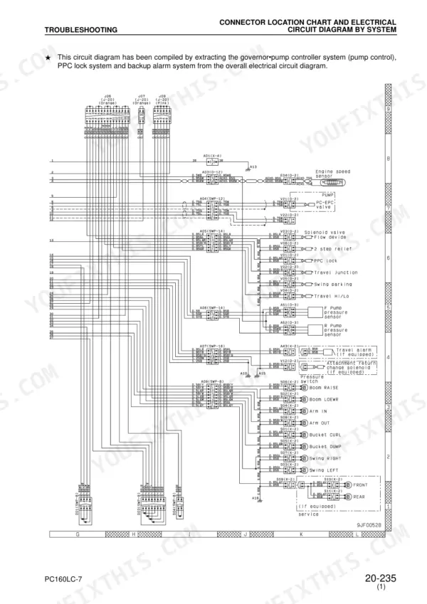
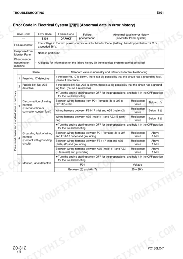
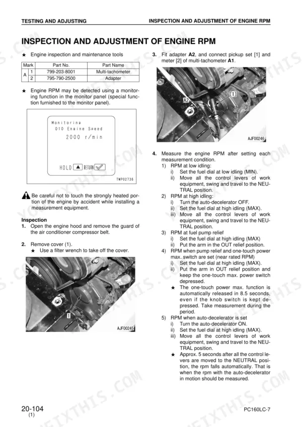
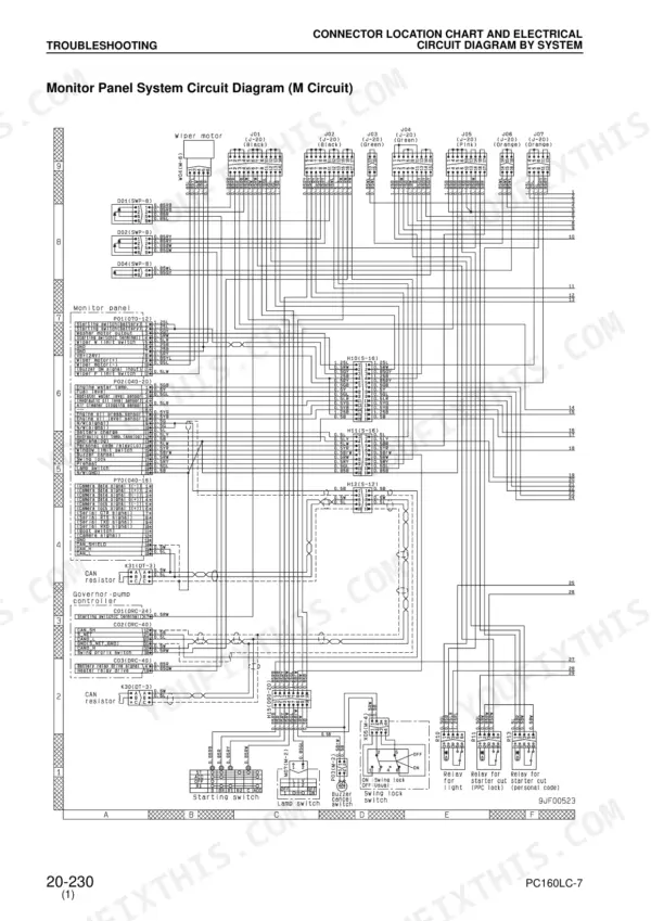
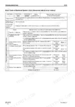
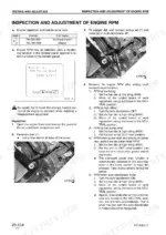
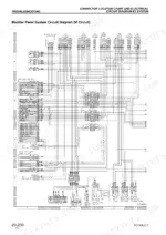
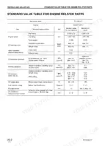
Within the hour you could have a T-adapter clipped into a solenoid connector and this 326-page Komatsu PC160LC-7 shop manual PDF (SEBM028601) open to the matching E-mode error code for your hydraulic excavator. Electrical troubleshooting fills nearly half the book, pairing each error code with circuit diagrams, connector pin tables, and sensor and solenoid checks that finish on a measured value. Hydraulic schematics and H-mode charts trace slow work equipment, weak swing, and travel faults back to the pumps and solenoids, and the testing section supplies standard value tables for engine and chassis parts. Expect 20 to 60 Ω across a healthy travel speed shifting solenoid, and torque the air bleeders to 27.5 to 35.3 Nm. An intermittent sensor fault can burn a whole shift. Bookmarked, text-searchable pages let you confirm the failed component before you order, so the part on the invoice is the right one the first time.
What's Inside This Komatsu PC160LC-7 Manual
| System | Pages | Key Topics |
|---|---|---|
| General | 1 | |
| Structure, Function and Maintenance Standard | 2-6 | |
| Testing and Adjusting | 7-92 | Standard Value Table for Engine Related Parts, Standard Value Table for Chassis Related Parts, Tools for Testing, Adjusting and Troubleshooting |
| Troubleshooting Fundamentals | 93-104 | Troubleshooting Sequence, Maintenance Precautions, Checks Before Troubleshooting, Connector Location Charts |
| Troubleshooting Classification and Steps | 105-152 | Troubleshooting Steps, Failure-Looking Phenomena, Connector Pin Connection Tables, T-Adapter Tables |
| Troubleshooting Error Code | 153-243 | Error Codes, Electrical System Troubleshooting, Circuit Diagrams, Sensor and Solenoid Diagnostics |
| Before Conducting E-Mode Troubleshooting | 244-298 | |
| Troubleshooting Hydraulic and Mechanical System (H-Mode) | 299-326 | Hydraulic System Charts, Work Equipment Speed and Power, Swing System Troubleshooting, Travel System Troubleshooting |
Quick Reference Specifications
| Specification | Value | Page |
|---|---|---|
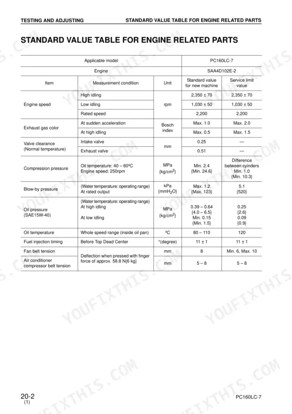
| Fan belt tension | 8 mm | p. 8 |
| Air conditioner compressor belt tension | 5 – 8 mm | p. 8 |
| Travel speed shifting solenoid valve functioning condition (front or rear pump pressure) | 29.4 MPa {300 kg/cm2} or 15.3 MPa {156 kg/cm2} | p. 48 |
| Air bleeder torque | 27.5 – 35.3 Nm {2.8 – 3.6 kgm} | p. 58 |
| Travel speed shifting solenoid resistance value | 20 – 60 Ω | p. 184 |
| Air cleaner clogging switch resistance (normal condition) | Below 1 Ω | p. 235 |
| Monitor panel voltage (normal condition) | Below 1 V | p. 235 |
| Air conditioner unit voltage | 20 – 30 V | p. 294 |
| Engine High Idling Speed | 2,350 ± 70 rpm | p. 8 |
| Engine Low Idling Speed | 1,030 ± 50 rpm | p. 8 |
| Intake Valve Clearance | 0.25 mm | p. 8 |
| Exhaust Valve Clearance | 0.51 mm | p. 8 |
Komatsu PC160LC-7 Common Problems This Manual Covers
Komatsu PC160LC-7 travel speed shifting solenoid circuit fault, travel speed stays in Lo when Hi is selected
Disconnect the travel speed shifting solenoid and measure resistance following page 184; a good coil reads 20 to 60 Ω. With Hi selected during travel, check governor and pump controller output for 20 to 30 V; below 1 V is the Lo or neutral reading. Confirm the solenoid valve functioning condition of 29.4 MPa or 15.3 MPa front or rear pump pressure on page 48.
Manual Section: Troubleshooting Electrical System (E-Mode) p. 184Air cleaner clogging switch suspect, clogging warning on the monitor panel stays lit
Disconnect the air cleaner clogging switch and measure resistance following page 235; a normal switch reads below 1 Ω. Then check monitor panel voltage: below 1 V is normal, 20 to 30 V signals clogged. If the switch reads normal but the panel still shows clogged, check the wiring against the E-Mode wiring diagrams.
Manual Section: Mechanical System Failure Codes p. 235Engine rotates unstably with idle speed hunting at low and high idle
Measure engine speed against the values on page 8: low idle 1,030 ± 50 rpm, high idle 2,350 ± 70 rpm. If readings wander, work the unstable rotation steps under Engine Troubleshooting, and verify the engine speed sensor nut is torqued to 49.0 to 68.6 Nm per page 32 before chasing fuel or controller faults.
Manual Section: Engine TroubleshootingAir conditioner unit does not operate when switched on from the operator cab
Measure voltage at the air conditioner unit following page 294; you need 20 to 30 V. If voltage is good, check compressor belt tension: deflection should be 5 to 8 mm under a 58.8 N (6 kg) depressing force, as listed on pages 8 and 33. Adjust belt tension before condemning the unit.
Manual Section: Attachment Troubleshooting p. 294Machine travel deviation, excavator drifts to one side when traveling straight on level ground
Check machine deviation with the H-Mode charts starting page 299 first. If the travel circuit checks out, set the travel deviation adjusting plug following page 54 and torque its lock nut to 2.9 to 4.9 Nm. After opening travel lines, bleed the travel motor and torque the air bleeder to 27.5 to 35.3 Nm per page 59.
Manual Section: Troubleshooting Hydraulic and Mechanical System (H-Mode) p. 299Boom, arm and bucket speed slow and digging power low on all work equipment
Check work equipment speed and power using the H-Mode charts from page 299 before adjusting anything. If main relief low pressure needs resetting, torque the adjustment lock nut to 49.0 to 58.8 Nm per page 38. After any pump work, bleed air at the hydraulic pump air bleeder and torque it to 27.5 to 35.3 Nm per page 58.
Manual Section: Troubleshooting Hydraulic and Mechanical System (H-Mode) p. 299Frequently Asked Questions
How do I reset the electrical system or failure history on a Komatsu PC160LC-7?
Resetting the electrical system failure history is possible only for the electrical system, while the mechanical system failure history cannot be reset. To reset, call the resetting display in the Electrical Systems menu using the switch operation [Δ] + [1] -> [2] -> [3]. Once in the resetting display, you can reset specific information or all information using the [Δ] or [∇] switches. p. 76
What do Komatsu PC160LC-7 error codes E02 and E03 mean?
Error code E02 indicates an error in the pump control system, requiring the emergency pump driving switch to be set to the ON position. Error code E03 indicates an error in the swing brake system, requiring the swing holding brake release switch to be set to the ON position to release the brake. p. 66
How do I access the PC160LC-7 service menu and error-code history?
To access the Service Menu, ensure the monitor is displaying ordinary items, then perform the switch operation [Δ] + [1] -> [2] -> [3]. From the Service Menu, select '02 Abnormality Record' to view failure history for electrical or mechanical systems. p. 70
What are the tightening torque specifications for PC160LC-7 hydraulic plugs?
The tightening torque for the hydraulic pump air bleeder is 27.5 – 35.3 Nm {2.8 – 3.6 kgm}. The lock nut for the travel deviation adjusting plug is 2.9 – 4.9 Nm {0.3 – 0.5 kgm}. p. 54
How do I troubleshoot a PC160LC-7 pump solenoid power-low error?
If the solenoid power supply (FB1-2) is defective, error codes such as E212, E213, E214, E215, E216, E233, or E248 may appear. Check the related fuse (FB1-2) and measure the voltage at connector C03 between pins (2) and (12) and ground pins (31), (32), and (33). The voltage should be 20 – 30 V. p. 160
Do I get instant access to this Komatsu PC160LC-7 Shop Manual?
You download the Shop Manual yourself: 326 pages, searchable PDF, available immediately. Keep a copy on every device you use.
Can I print just the pages I need from this Komatsu PC160LC-7 manual?
Yes. Print the pages you need for the job in your own shop, and bin them when they get greasy.


Reviews
There are no reviews yet.