
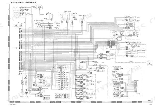
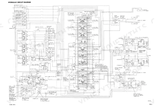
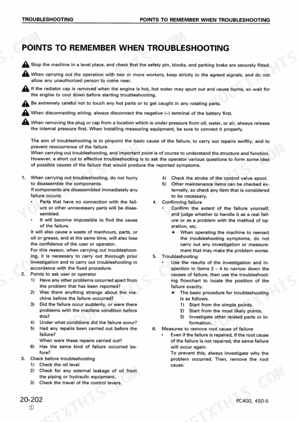
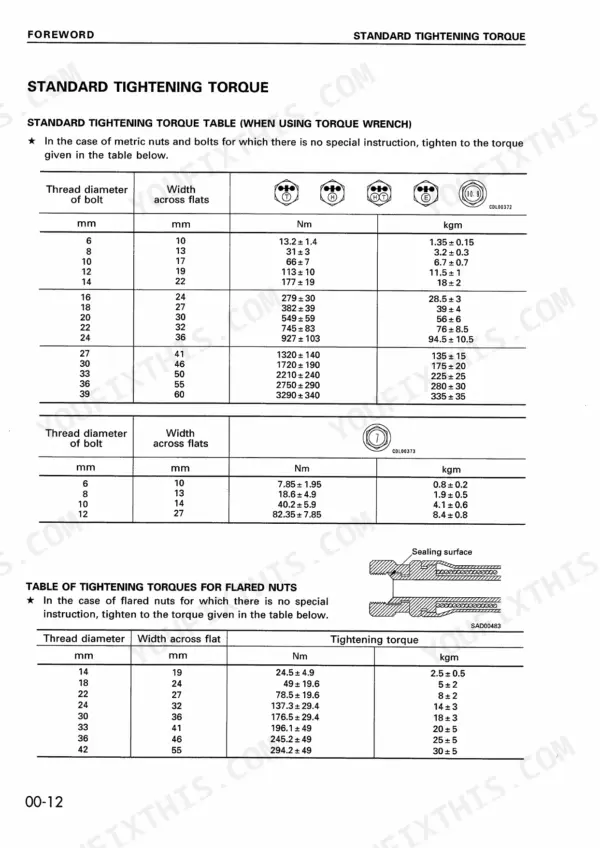
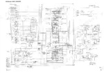
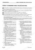
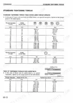
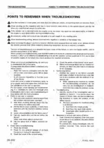
Bringing a high-hour PC400-6 series hydraulic excavator back to Komatsu standard values is the job these 892 pages of shop manual SEBM014507 were written for, across four variants. Testing and Adjusting fills the largest share of this Komatsu PC400-6, PC400LC-6, PC450-6, PC450LC-6 shop manual PDF with standard value tables for engine and chassis parts, while Structure and Function traces the piping, hydraulic pump and control valve. Disassembly and Assembly walks you through the fuel injection pump and oil cooler, Maintenance Standard sets wear limits for swing machinery and final drive, and the back of the book holds the hydraulic and electric circuit diagrams. Confirm the PPC hydraulic switch turns on at 0.5 ± 0.1 MPa and resets at 0.3 ± 0.05 MPa. A dead pilot circuit with no diagram costs a full shift. Bookmarks put you on the circuit diagrams or any standard value table in seconds, and a keyword search finds the part name you type.
What's Inside This Komatsu PC400-6, PC400LC-6, PC450-6, PC450LC-6 Manual
| System | Pages | Key Topics |
|---|---|---|
| General | 1-48 | Specification Drawings, Specifications, Fuel, Coolant and Lubricants |
| Structure and Function | 49-273 | Hydraulic Piping Drawing, Hydraulic Pump, Control Valve |
| Testing and Adjusting | 274-599 | Standard Value Table for Engine Related Parts, Standard Value Table for Chassis Related Parts |
| Disassembly and Assembly | 600-823 | Special Tool List, Engine Oil Cooler, Fuel Injection Pump |
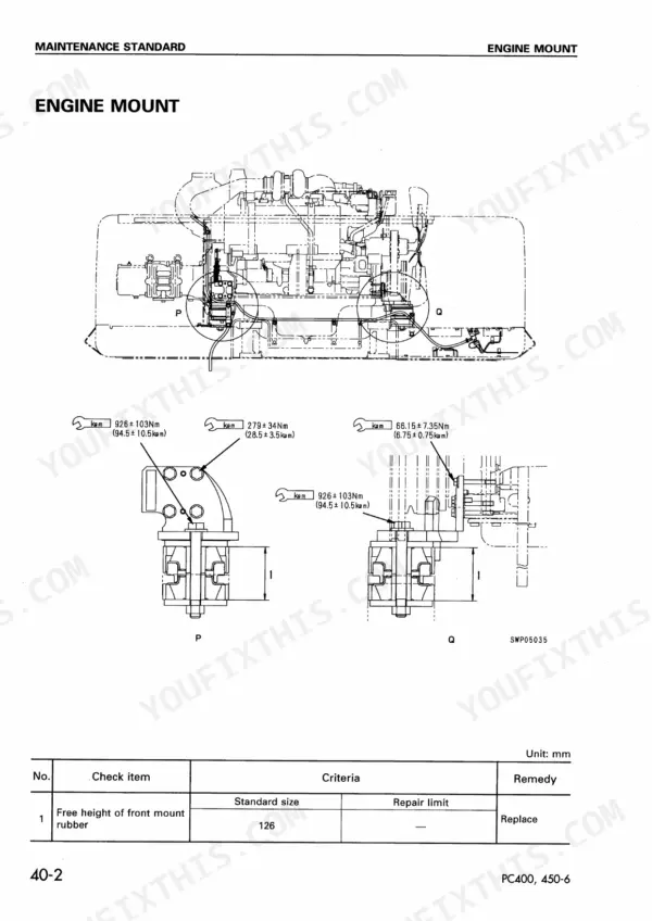
| Maintenance Standard | 824-879 | Engine Mount, Swing Machinery, Final Drive |
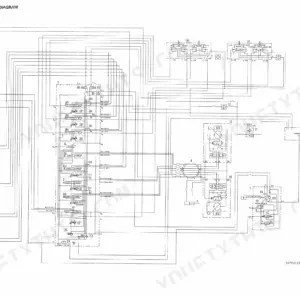
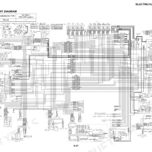
| Others | 880-892 | Hydraulic Circuit Diagram, Electric Circuit Diagram |
Quick Reference Specifications
| Specification | Value | Page |
|---|---|---|
| Suction cracking pressure | 0 - 0.49 kPa | p. 67 |
| Bypass valve set pressure | 102.9 ± 19.6 kPa | p. 67 |
| Relief cracking pressure | 16.7 ± 6.9 kPa | p. 67 |
| PPC hydraulic switch Actuation (ON) pressure | 0.5 ± 0.1 MPa | p. 257 |
| PPC hydraulic switch Reset (OFF) pressure | 0.3 ± 0.05 MPa | p. 257 |
| TVC prolix resistor resistance | 8.5 Ω | p. 259 |
| Muffler band | 9.8 ± 2.0 Nm | p. 623 |
| Hose clamp | 4.4 ± 0.5 Nm | p. 623 |
| Hydraulic tank mounting bolt | 277.0 ± 31.9 Nm | p. 729 |
| Piston | 475.6 ± 34.3 Nm | p. 737 |
| Hydraulic tank | 280 L | p. 730 |
| Damper case | 1.1 L | p. 744 |
Komatsu PC400-6, PC400LC-6, PC450-6, PC450LC-6 Common Problems This Manual Covers
Komatsu PC400-6 monitor panel and engine throttle, pump controller network displaying E218 communication abnormality
Check that all related connectors are properly inserted, then turn the starting switch on; if service code E218 no longer displays, the problem has cleared. If it persists, read monitoring codes 02, 03 and 08 on page 395, disconnect C17 and P01, and measure resistance between P01 (4), (11) and chassis: Min. 1 MΩ. Press lock stoppers with your thumb and never pull connectors apart with one hand (page 351).
Manual Section: Troubleshooting of communication abnormality system (N mode) p. 395Governor motor and injection pump linkage with no code displayed, engine hunting or not stopping
Disconnect governor motor connector E05 before disconnecting the rod (page 624), and never move the governor motor lever suddenly. Free the linkage to the injection pump and work the pump lever by hand following page 399. If the condition returns to normal and the governor motor operates normally, adjust the linkage; if the motor stays abnormal, go to E-9 through E-12. No improvement means engine system troubleshooting S-1 through S-16.
Manual Section: Troubleshooting of engine throttle, pump controller (E mode) p. 399Governor motor feedback potentiometer E306 displayed, engine not reaching high idling speed or hunting
Check C03, E04 connectors for poor contact, then measure E04 per page 404: (1) to (2) and (2) to (3) at 0.25 to 7 kΩ, (1) to (3) at 4 to 6 kΩ, each pin to chassis Min. 1 MΩ. Out of range means a defective governor motor potentiometer; in range, trace the C03 to E04 harness for shorts or disconnection. Press the lock stopper with your thumb to separate connectors (page 351).
Manual Section: Troubleshooting of engine throttle, pump controller (E mode) p. 403Governor motor drive system E317 disconnection displayed, engine not stopping and speed uncontrollable
Check the E05 connector for defective contact, then disconnect E05 and measure the governor motor side following page 402: (1) to (2) and (3) to (4) at 0.25 to 7 kΩ, pins to chassis Min. 1 MΩ. An open reading means a disconnection inside the governor motor; good readings send you to the C02 to E05 harness listed on page 401. Disconnect E05 before moving the governor motor lever (page 312).
Manual Section: Troubleshooting of engine throttle, pump controller (E mode) p. 401Fuel control dial E308 input abnormality displayed, engine speed stuck at previous dial position
Check connectors C03, X07 and E06 for defective contact, then disconnect E06 and measure the dial side following page 402: (1) to (2) and (2) to (3) at 0.25 to 7 kΩ. Out of range means a defective fuel control dial; in range, check the C03, X07, E06 harness for the shorts or disconnections listed on page 401. Press the lock stopper with your thumb to separate connectors (page 351).
Manual Section: Troubleshooting of engine throttle, pump controller (E mode) p. 401Engine oil pressure caution lamp lights up with drop in oil pressure
Check that the monitor panel engine oil level lamp is not lit and that the oil pressure sensor tests normal in M mode, following page 448. Then start the engine and measure oil pressure following page 308: the low-pressure sensor caution end at low idling, the high-pressure sensor caution end at high idling.
Manual Section: Troubleshooting of engine system (S mode) p. 448Frequently Asked Questions
How do you reset the service code display on the monitor panel for a PC400-6 or PC450-6?
To erase service codes from the internal memory, turn the starting switch OFF. Then, keep the time switch on the back of the monitor panel depressed, switch the starting switch ON again, and continue to hold the time switch for 5 seconds. This operation will erase all service codes stored in the internal memory. p. 377
What causes weak engine power on a Komatsu PC400-6 or PC450-6?
Weak engine power can be caused by insufficient intake of air, insufficient supply of fuel, improper condition of fuel injection, improper fuel used, or lack of output due to overheating. You should check the air cleaner, fuel filters, and injection timing as detailed in the troubleshooting section on page 442. p. 442
What is the standard tightening torque for the cylinder head mounting bolts on the PC400-6 and PC450-6?
The cylinder head mounting bolts must be tightened in three steps. The first pass is 98.1 ± 9.8 Nm (10 ± 1 kgm), the second pass is 137.3 ± 4.9 Nm (14 ± 0.5 kgm), and the third pass is 90 degrees using an angle tightening wrench or by marking the bolt head. p. 642
What is the standard capacity for the hydraulic tank on the PC400-6 and PC450-6?
The hydraulic tank capacity is approximately 270 liters for the PC400-6 and PC450-6 models. p. 728
What is the standard intake and exhaust valve clearance for the SA6D125E-2 engine in a Komatsu PC400-6 excavator?
The standard valve clearance for the intake valve is 0.34 mm and for the exhaust valve is 0.71 mm. p. 275
Is this Komatsu PC400-6 manual a PDF I download?
This is a 892-page searchable PDF ready for immediate download. Works on any device, so pull it up on your phone while you're under the hood. No shipping, no waiting.
Can I print this Komatsu PC400-6 manual?
Yes. Print a chapter or just the pages for the job at hand, for use in your own shop. Any home or office printer works.



Reviews
There are no reviews yet.