
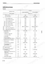
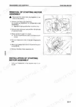
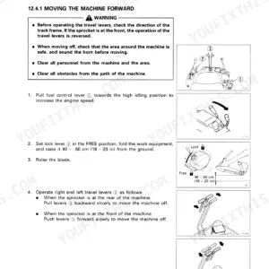
Only Komatsu can settle what a healthy machine should read on the gauge, and this 473-page Komatsu PC20R-8, PC25R-8, PC27R-8 shop manual PDF (SEBM010801) puts those factory standard values in writing for all three hydraulic excavators. Testing and adjusting fills a large share of the book: standard value tables for engine, chassis and electrical, plus troubleshooting charts that trace a fault to its source. Hydraulic circuit diagrams follow the CLSS piping from pump to control valve, wiring diagrams cover the electrical side, and the longest section takes you through rebuilding the fuel injection pump and hydraulic cylinders. On the PC25R-8 and PC27R-8, refill the hydraulic system with 29 L after a service (50 L specified; the PC20R-8 takes 25 L of 40 L) and torque the swing motor safety valve locknut to 90.65 ± 12.25 Nm. Tracing a sluggish circuit on a machine this compact is cramped work. Bookmarked and text-searchable, the PDF rides on your laptop or phone, so it sits wherever the excavator is parked.
What's Inside This Komatsu PC20R-8, PC25R-8, PC27R-8 Manual
| System | Pages | Key Topics |
|---|---|---|
| General | 1-41 | Safety Notice, Hoisting Instructions, Coating Materials |
| Structure and Function | 42-138 | Power Train, Hydraulic Piping, Hydraulic Pump, Control Valve |
| Testing and Adjusting | 139-261 | Standard Value Table for Engine, Standard Value Table for Chassis, Standard Value Table for Electrical |
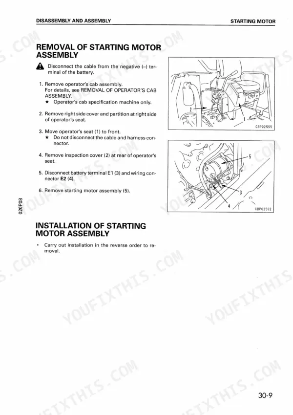
| Disassembly and Assembly | 262-431 | Starting Motor, Fuel Injection Pump, Hydraulic Cylinder |
| Maintenance Standard | 432-464 | Swing Circle, Track Roller, Work Equipment |
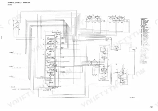
| Others | 465-473 | Hydraulic Piping, Hydraulic Circuit Diagram, CLSS Operation |
Quick Reference Specifications
| Specification | Value | Page |
|---|---|---|
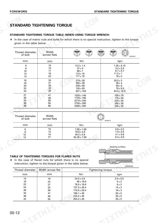
| Standard tightening torque for metric nuts and bolts (6 mm) | 13.2 ± 1.4 Nm | p. 14 |
| Standard tightening torque for metric nuts and bolts (8 mm) | 31 ± 3 Nm | p. 12 |
| Hydraulic system oil refill capacity | 29 L | p. 40 |
| Hydraulic system oil specified capacity | 50 L | p. 40 |
| Swing motor safety valve locknut torque | 90.65 ± 12.25 Nm | p. 173 |
| PC20R work equipment relief pressure | 17.2 +0.49/0 MPa (175 +5/0 kg/cm²) | p. 230 |
| PC20R arm IN relief pressure | 17.2 +0.49/0 MPa (175 +5/0 kg/cm²) | p. 233 |
| PC25R work equipment relief pressure | 19.6 +0.49/0 MPa (200 +5/0 kg/cm²) | p. 230 |
| PC25R arm IN relief pressure | 19.6 +0.49/0 MPa (200 +5/0 kg/cm²) | p. 233 |
| PC27R work equipment relief pressure | 20.6 +0.49/0 MPa (210 +5/0 kg/cm²) | p. 230 |
| PC27R arm IN relief pressure | 20.6 +0.49/0 MPa (210 +5/0 kg/cm²) | p. 233 |
| Engine Oil Capacity (Specified) | 3.4L | p. 40 |
Komatsu PC20R-8, PC25R-8, PC27R-8 Common Problems This Manual Covers
Komatsu PC20R-8, PC25R-8, PC27R-8 boom, arm or bucket cylinder hydraulic drift exceeds standard value
Check the oil is at 45 to 55°C, fully extend the rod and stop the engine; if the circuit was relieved at stroke end, wait 5 to 10 minutes before any work (page 189). Disconnect only the head end piping, blind plug the chassis side, and hold relief at full throttle per page 188. After 30 seconds, measure one minute of leakage: within standard means control valve, outside means cylinder.
Manual Section: Measuring oil leakage inside cylinder p. 188Work equipment lacks power and main relief pressure reads out of standard at full throttle
Check the oil is at 45 to 55°C. Release hydraulic tank pressure before removing the measurement plug, and pressurize the tank after fitting the gauge, as page 170 warns. Hold each cylinder at stroke end at full throttle and read pressure. If off on a PC20R-8, loosen the main relief locknut, turn the screw clockwise to raise (12.6 MPa per turn), torque the locknut to 59 ± 10 Nm per page 171, then remeasure.
Manual Section: Testing and adjusting hydraulic pressure p. 170Swing lacks power and swing relief pressure reads out of standard at full throttle
Check swing relief with oil at 45 to 55°C. Release hydraulic tank pressure before pulling the plug and repressurize once the gauge is fitted (page 170). Lock the swing securely with the work equipment, run full throttle and read. If off, loosen the swing motor safety valve locknut, turn the screw clockwise to raise pressure, retighten the locknut per page 171, and remeasure.
Manual Section: Testing and adjusting hydraulic pressure p. 171LS differential pressure out of standard with travel lever at neutral or half stroke
Check LS differential: pump discharge to the gauge high side, LS pressure to the low side. Push one track up with the work equipment, run full throttle, and expect max 3.4 MPa at neutral and 1.57 MPa at half travel lever (page 174). If off, disconnect the hose and adjust the LS valve screw (1.3 MPa per turn), then recheck.
Manual Section: Testing and adjusting LS differential pressure p. 174Air trapped in pump, cylinders, swing motor and travel motor after hydraulic oil change
Fill the hydraulic tank without letting any dirt in (page 201). Then bleed in the page 190 order: pump, start the engine, cylinders, swing motor, travel motor, pressurize the hydraulic tank, then begin operations. Do not relieve the circuit under any circumstances while bleeding, as page 191 states.
Manual Section: Bleeding air p. 190Engine does not start, or engine does not stop with the starting switch turned OFF
Check fuel level, oil levels, battery terminals and electrical components before opening any E mode chart. Confirm the failure yourself and do not hurry to disassemble components, as page 193 warns, or you lose the real cause. When separating locked connectors, press the stopper with your thumb and never pull with one hand (page 197).
Manual Section: Troubleshooting of electrical system (E mode)Frequently Asked Questions
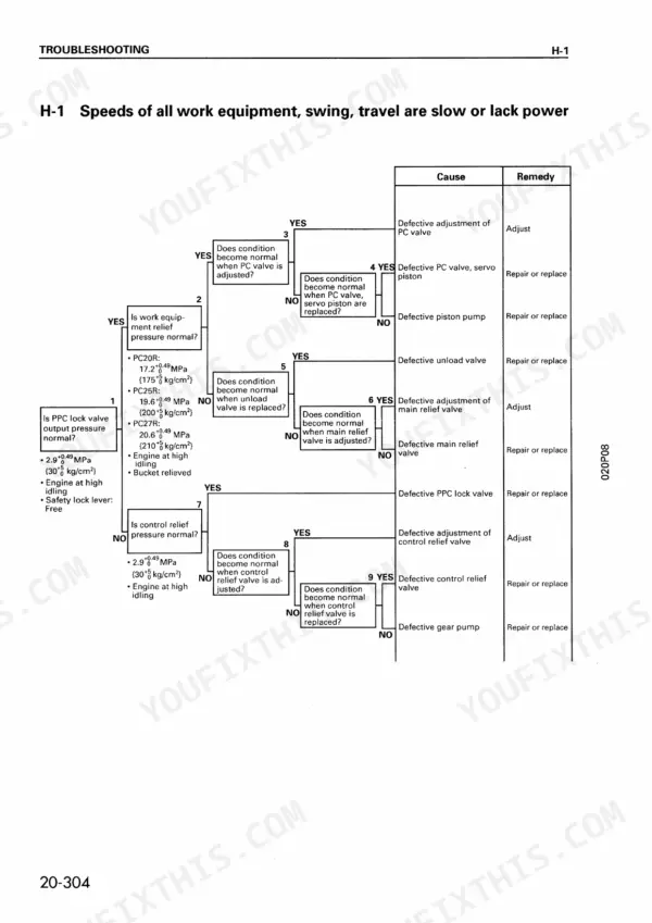
What causes hydraulic operation to be slow or weak on the PC20R-8?
Slow or weak hydraulic operation can be caused by a defective adjustment of the PC valve, a defective PC valve or servo piston, a defective piston pump, or a defective unload valve. Refer to the troubleshooting chart on page 230 for the specific diagnostic flow. p. 230
How do you bleed air from the hydraulic system after maintenance?
Bleeding air from the hydraulic system involves specific procedures for different components. For the pump, loosen air bleed plug (1) until oil flows without air bubbles, then tighten to 16.7 ± 2.5 Nm (1.7 ± 0.25 kgm). For cylinders, run the engine at low idling and cycle the boom 4-5 times, then repeat at full throttle. Refer to pages 190-191 for the complete air bleeding procedure. p. 190
What is the torque spec for the cylinder head assembly mounting bolts on the Komatsu PC20R-8, PC25R-8, PC27R-8?
The cylinder head assembly mounting bolts must be tightened to 68.6 ± 1.96 Nm (7 ± 0.2 kgm) in the order shown in the diagram on page 288. p. 288
What is the standard swing circle bearing axial clearance on the Komatsu PC20R-8, PC25R-8, PC27R-8?
The standard clearance for the bearing axial clearance on the swing circle is 0.03 - 0.13 mm. If the clearance reaches the limit of 0.23 mm, the bearing must be replaced. p. 433
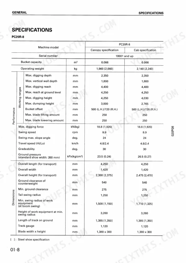
What is the capacity of the hydraulic tank for the PC20R-8?
The specified capacity for the hydraulic tank on the PC20R-8 is 40 liters, with a refill capacity of 25 liters. p. 40
Is this Komatsu PC20R-8 Shop Manual a digital download?
Delivery is instant: a 473-page searchable PDF is yours the second checkout clears. Laptop, tablet, or phone, all fine.
Are there any print restrictions on this Komatsu PC20R-8 manual?
You can. The PDF is unlocked and carries no copy protection, so print the sections you want and keep the file as your backup.



Reviews
There are no reviews yet.