
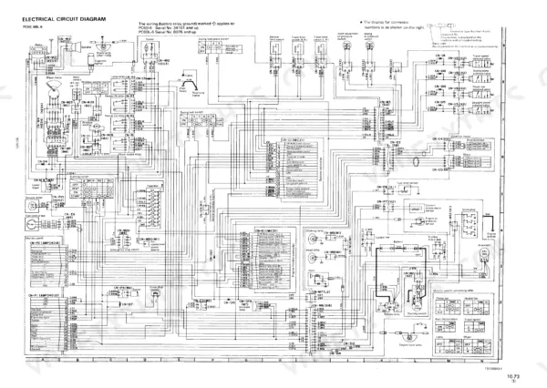
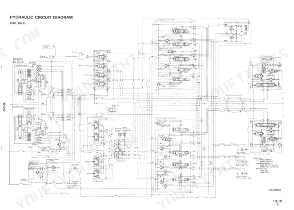
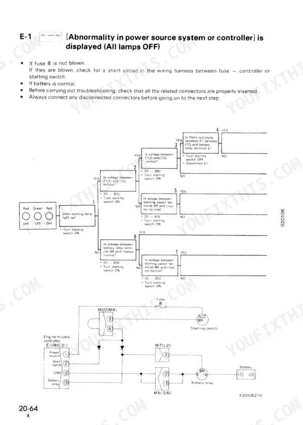
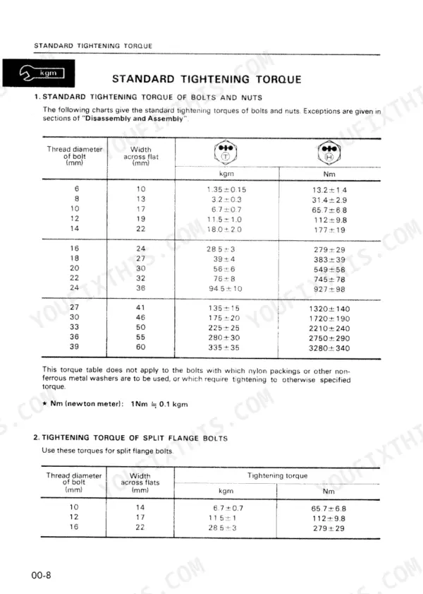
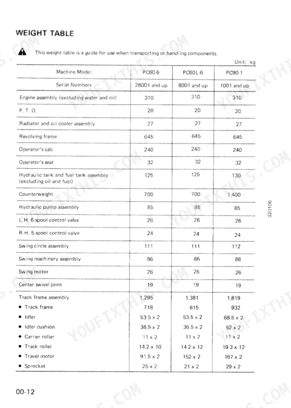
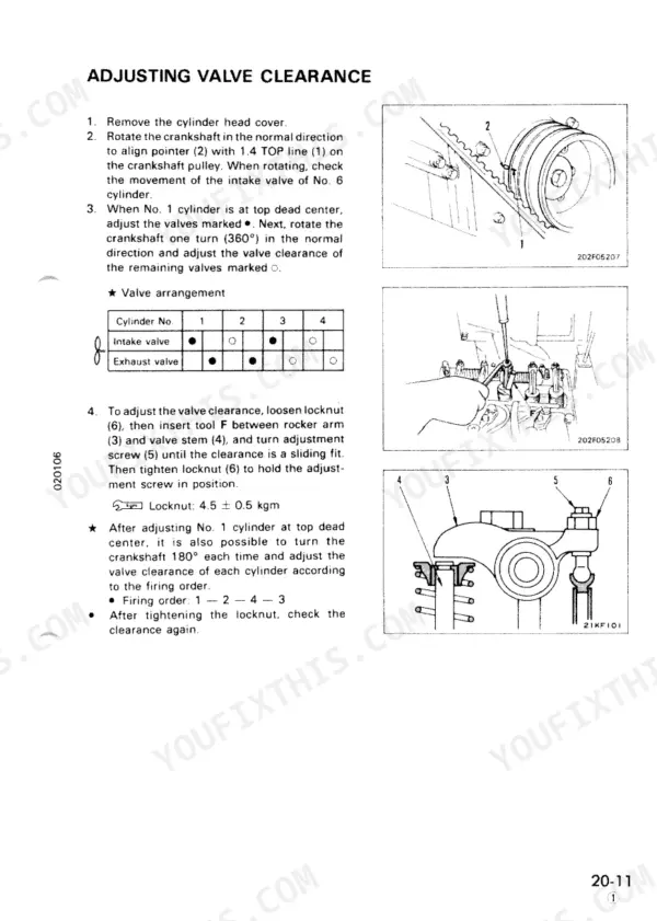
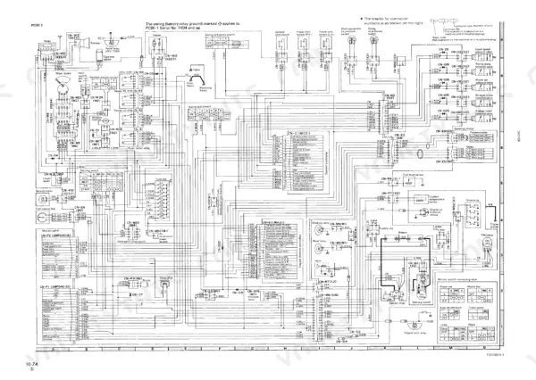
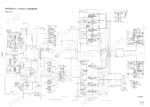
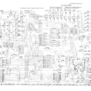
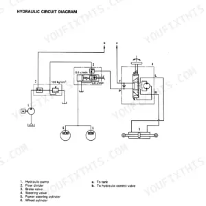
Before you crack a fitting on the swing machinery or pull a track roller today, open the Komatsu PC60-6, PC60L-6, PC90-1 shop manual PDF: 451 factory pages, OEM ID SEBM02010607, for all three hydraulic excavators. Hydraulic schematics trace the piping from pump through control valve to boom, arm and bucket cylinders, and wiring diagrams map the harness circuit by circuit. Structure and Function explains each system; Testing and Adjusting, a third of the book, carries standard value tables and troubleshooting charts; Disassembly and Assembly takes the pump, swing machinery and cylinders apart; Maintenance Standard sets wear limits on swing circle, track rollers and control valve. Set PPC valve disc-to-piston clearance at 0.3 to 0.5 mm, and run 12 mm bolts to 112 ± 9.8 Nm. A misread pump fault means a second teardown and a crew parked all day. The bookmarked, text-searchable PDF helps you confirm what failed, so the first part you order is the right one.
What's Inside This Komatsu PC60-6, PC60L-6, PC90-1 Manual
| System | Pages | Key Topics |
|---|---|---|
| Structure and Function | 16-133 | Engine Mount and Related Parts, Swing Machinery, Track Frame, Hydraulic Piping |
| Testing and Adjusting | 134-290 | Standard Value Table, Troubleshooting |
| Disassembly and Assembly | 291-400 | Engine Related Parts, Hydraulic Pump Assembly, Swing Machinery Assembly, Hydraulic Cylinder Assembly |
| Maintenance Standard | 401-451 | Swing Circle Standard, Track Frame Standard, Track Roller Standard, Control Valve Standard |
Quick Reference Specifications
| Specification | Value | Page |
|---|---|---|
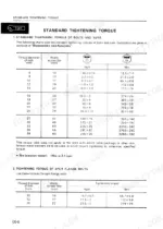
| Standard tightening torque for 6mm bolt | 1.35 ± 0.15 kgm (13.2 ± 1.4 Nm) | p. 10 |
| Standard tightening torque for 8mm bolt | 3.2 ± 0.3 kgm (31.4 ± 2.9 Nm) | p. 10 |
| Hydraulic tank relief set pressure | 0.39 ± 0.15 kg/cm² | p. 37 |
| Hydraulic tank suction set pressure | 0 - 0.046 kg/cm² | p. 37 |
| Clearance between disc and piston (PPC valve) | 0.3 - 0.5 mm | p. 167 |
| Spring installed load (Servo piston) | Approx. 60 kg | p. 352 |
| Spring installed load (Cylinder block) | Approx. 130 kg | p. 353 |
| Clearance between rotor and shaft (PC60-6, 60L-6, PC90-1) | 0.056 - 0.105 mm | p. 443 |
| Clearance between rotor and shaft (PC60-6 with blade) | 0.056 - 0.105 mm | p. 443 |
| PPC Valve Pilot spring free length x O.D. | 12.6 x 3.85 mm | p. 444 |
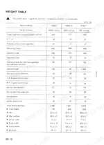
| Engine Oil Pan Capacity (Specified) | 8.0L | p. 15 |
| Engine Oil Pan Capacity (Refill) | 7.0L | p. 15 |
Komatsu PC60-6, PC60L-6, PC90-1 Common Problems This Manual Covers
Komatsu PC60-6 center swivel joint leaking internally, machine deviates to one side during straight travel
Park on level ground and check the safety pin and chock before testing (page 134). Measure travel deviation at high idle over 20 m of hard, flat ground after a 10 m run-up. Then test the center swivel joint for oil leakage, relieving the circuit being measured, against the limits on page 141. On teardown, check rotor-to-shaft clearance against 0.056 to 0.105 mm.
Manual Section: Testing and Adjusting Procedures p. 141Boom, arm or bucket cylinder retracts and bucket teeth drop with control levers at neutral
Park on level ground and check the safety pin and chock first (page 134). Set the bucket with rated load on horizontal, flat ground, levers at neutral, engine stopped. Measure cylinder retraction and drop at the bucket teeth every 5 minutes, then judge from the 15 minute result against the hydraulic drift table on page 140.
Manual Section: Hydraulic and Mechanical System (H Mode) p. 140Upper structure drifts downhill on a slope with swing stopped and engine off
Stop the engine, set the machine on the specified slope with the upper structure turned to the side, and make match marks on the swing circle outer race and track frame. Measure how far they move apart after 5 minutes. Then check swing motor leakage at high idle with the swing lock switch ON, relieving the swing circuit, against page 138.
Manual Section: Hydraulic and Mechanical System (H Mode) p. 138PPC valve out of adjustment, work equipment control lever shows excessive play at neutral
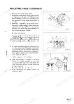
Measure PPC valve output pressure first, then adjust the valve: remove the boot, loosen the locknut and screw in the disc until it contacts the heads of the four pistons. Do not operate the pistons while adjusting (page 168). Hold the disc in position, tighten the locknut, and confirm disc-to-piston clearance of 0.3 to 0.5 mm.
Manual Section: Testing and Adjusting Procedures p. 167Work equipment, travel and swing speeds are all slow with power set in S mode
Test main pump discharge volume with hydraulic oil at operating temperature, bringing pump pressures P1 and P2 close to the average pressure and avoiding the bend in the graph. Compare results against the graph for your model and mode on pages 143 to 146. If the fuel control dial cannot reach rated speed, calculate discharge from actual engine speed.
Manual Section: Hydraulic and Mechanical System (H Mode) p. 143Engine throttle controller fault, engine does not stop when starting switch is turned OFF
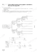
Check the governor motor and fuel control dial circuits by working through the E mode troubleshooting tables. When separating connectors, release the lock and pull in parallel with both hands, never with one hand (page 200). Do not open the control box cover unless necessary, and keep it out of rain (page 183). Then adjust governor motor lever travel.
Manual Section: Engine Throttle Controller System (E Mode)Frequently Asked Questions
How do I reset the self-diagnostic display on the engine throttle controller?
Once the starting switch is turned OFF, the self-diagnostic display is reset. You should check the abnormal display with the starting switch turned ON. p. 201
What are the hydraulic pressure test values for the main relief valve on the PC90-1?
When work equipment and swing are operated, the set pressure is 325 kg/cm² at 27 l/min. When traveling, the set pressure is 355 kg/cm² at 24 l/min. p. 57
What is the valve clearance specification for the 4D95L-1 engine in the Komatsu PC60-6, PC60L-6, PC90-1?
The valve clearance for both the intake and exhaust valves at normal temperature is 0.35 mm for intake and 0.50 mm for exhaust. p. 135
What is the tightening torque for the cylinder head mounting bolts on the PC60-6?
The cylinder head mounting bolts are tightened in three steps: 7 kgm for the first step, 11 kgm for the second step, and then tightened an additional 90 degrees for the third step. p. 299
What is the fuel tank capacity for the Komatsu PC90-1?
The fuel tank capacity for the PC90-1 is 200 liters. p. 301
Will this Komatsu PC60-6 Shop Manual download right away?
You download the Shop Manual yourself: 451 pages, searchable PDF, available immediately. Keep a copy on every device you use.
Can I print a copy of this Komatsu PC60-6 Shop Manual for the shop?
Yes. Print the pages you need for the job in your own shop, and bin them when they get greasy.


Reviews
There are no reviews yet.