
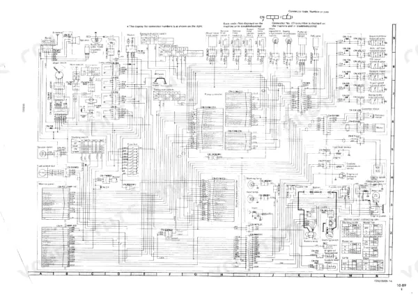
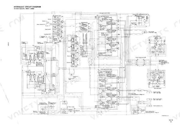
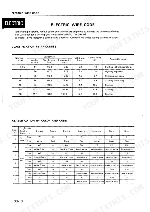
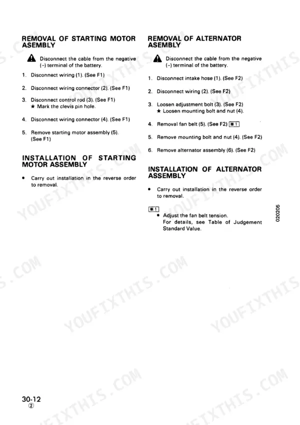
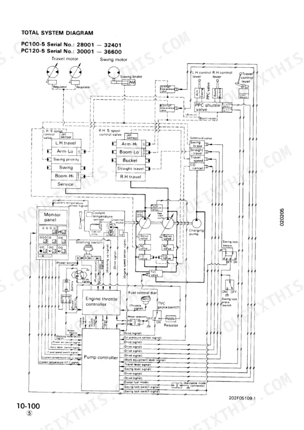
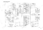
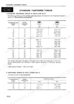
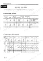
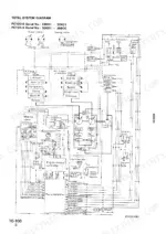
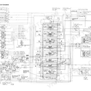
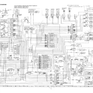
When a swing motor goes lazy or a final drive starts weeping oil, the Komatsu PC100-5, PC120-5 shop manual PDF (OEM ID SEBM02020508) puts 644 pages of factory data behind your repair, covering both hydraulic excavators plus the PC120-5 Mighty. Testing and Adjusting is the heaviest chapter, roughly two fifths of the book, built around the standard value table, hydraulic pressure checks and troubleshooting charts that walk a fault from symptom to failed component. Hydraulic schematics show oil routing from pump to cylinders, wiring diagrams trace the electrical circuits, and the Maintenance Standard sets wear limits for final drive, swing machinery and track rollers. Refill the hydraulic system with 100 L of its 150 L total and keep 12 L in the engine oil pan. A guessed relief pressure can split a hose. Bookmarks take you straight to the right chapter, and text search lands on any spec in seconds.
What's Inside This Komatsu PC100-5, PC120-5, PC120-5 MIGHTY Manual
| System | Pages | Key Topics |
|---|---|---|
| Structure and Function | 25-190 | Engine Related Parts, Hydraulic Tank and Fuel Tank, Hydraulic Pump |
| Standard Value Table | 192-235 | Table of Judgement Standard Value, Standard Value Table for Electrical System, Adjusting Valve Clearance, Measuring Compression Pressure |
| Testing and Adjusting Hydraulic Pressure | 236-261 | Testing and Adjusting Charging Pump Pressure, Testing and Adjusting Main Pump Control Pressure, Testing and Adjusting Travel Deviation, Adjusting PPC Valve, Bleeding Air |
| Troubleshooting | 262-448 | Troubleshooting of Pump Controller System (C Mode), Troubleshooting of Pump Controller Input Signal System (F Mode), Troubleshooting of Hydraulic and Mechanical System (H Mode), Troubleshooting of Monitor System (P Mode) |
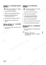
| Disassembly and Assembly | 449-607 | Starting Motor and Alternator, Engine Oil Cooler and Fuel Injection Pump, Water Pump and Nozzle Holder |
| Maintenance Standard | 608-644 | Final Drive, Swing Machinery, Track Roller |
Quick Reference Specifications
| Specification | Value | Page |
|---|---|---|
| All Models | ||
| Engine oil pan capacity (Specified) | 12 L | p. 22 |
| Hydraulic system capacity (Refill) | 100 L | p. 22 |
| Hydraulic System Capacity (Specified) | 150L | p. 24 |
| Fuel tank capacity | 250 L | p. 52 |
| Fuel Tank Capacity (Specified) | 250L | p. 24 |
| Arm cylinder rod outside diameter | 75 mm | p. 130 |
| Arm cylinder inside diameter | 115 mm | p. 130 |
| Hydraulic drift (no load) - PC120 Boom | Max. 10 mm | p. 396 |
| PC100-5 Serial No. 28001-29805, PC120-5 Serial No. 30001-32304 | ||
| Hydraulic tank capacity | 150 L | p. 52 |
| Hydraulic tank oil amount | 100 L | p. 52 |
| PC100-5 | ||
| Governor motor linkage angle (PC100) | 48° ± 4°12' | p. 142 |
| PC120-5 | ||
| Governor motor linkage angle (PC120) | 50° ± 4°12' | p. 142 |
Komatsu PC100-5, PC120-5, PC120-5 MIGHTY Common Problems This Manual Covers
Komatsu PC100-5 and PC120-5 engine throttle controller shows power source abnormality with all lamps off
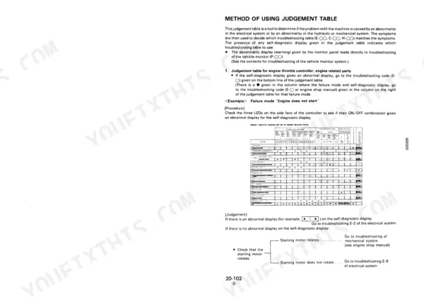
Check fuses 2 and 8. If one is blown, look for a short in the harness between the fuse and the controller or starting switch. Make sure all related connectors are seated. When you disconnect one, release the lock and pull straight with both hands (page 299). Turn the switch ON and measure E1 and starting switch terminal ACC against 20-30V, following page 319. Then repair the harness or replace the battery relay, starting switch or controller.
Manual Section: Engine Throttle Controller System (E Mode) p. 319Governor motor short circuit displayed, engine starts but stays at low idling and will not stop
Stop the engine before any check by placing the injection pump governor lever in the NO INJECTION position, as page 323 directs. Turn the starting switch OFF, disconnect E1 and E5, and measure resistance from the governor motor pins to chassis against min. 1 MΩ. Repair a shorted harness, replace a defective governor motor, or replace the engine throttle controller.
Manual Section: Engine Throttle Controller System (E Mode) p. 323Engine throttle control hunts or high idling speed is too low with no self-diagnostic display
Disconnect the linkage between the governor motor and injection pump, set the starting switch ON, and operate the pump governor lever by hand per page 318. If the engine runs normally, check the governor motor. If the motor works, adjust the linkage to the angle on page 142. If it does not, go to E-9 through E-11. If the fault persists by hand, see the engine shop manual.
Manual Section: Engine Throttle Controller System (E Mode) p. 318Boom, arm or bucket cylinder drifts down while the control levers sit in neutral
Park on level ground and check the safety pin and chock before you measure, per page 191. Measure no-load hydraulic drift and compare it to the PC120 limits on page 396: boom max. 10 mm, arm max. 80 mm, bucket max. 40 mm. Confirm the reading before you tear anything down, because page 263 warns against hurrying to disassemble components.
Manual Section: Hydraulic and Mechanical System (H Mode) p. 396Work equipment, travel and swing do not move or speed is extremely slow
Check the pump controller self-diagnostic display first, because page 312 says it tells you which troubleshooting table to use. Set the working mode to H.O or H mode and measure the speeds, following page 391. Run the flow only when there is a big difference from the permissible value. Do not hurry to disassemble components (page 263).
Manual Section: Hydraulic and Mechanical System (H Mode) p. 391Monitor panel engine oil pressure CAUTION lamp flashes after the engine is started
Verify that actual engine oil pressure is at the standard value before you troubleshoot the monitor circuit, as page 426 directs. If pressure is good, follow the P-7 flow through the engine oil pressure sensor and wiring. If the lamp also lights with the starting switch ON and the engine stopped, do not start the engine. Follow the P-6 checks on page 425 instead.
Manual Section: Monitor System (P Mode) p. 426Frequently Asked Questions
How do I troubleshoot slow hydraulics on a Komatsu PC120-5 MIGHTY?
To troubleshoot slow hydraulics, first check if the problem occurs in H.O mode or other modes. If it occurs only in H.O mode, check the pressure at the outlet port of the CO cancel solenoid valve, which should be 25-35 kg/cm². If the pressure is normal, the CO valve may be defective and require replacement. If the problem occurs in other modes, check the relief pressure when the main relief valve is adjusted. p. 393
How do I adjust the travel speed on a Komatsu PC100-5?
The travel speed switching is controlled by the travel speed solenoid valve. If the travel speed does not switch, check the hydraulic pressure at the outlet port of the travel speed solenoid valve, which should be 25-35 kg/cm² at Hi and 0 kg/cm² at Lo. If the pressure is incorrect, the travel speed solenoid valve may need to be replaced. p. 409
What is the standard tightening torque for the cylinder head mounting bolts on a PC100-5?
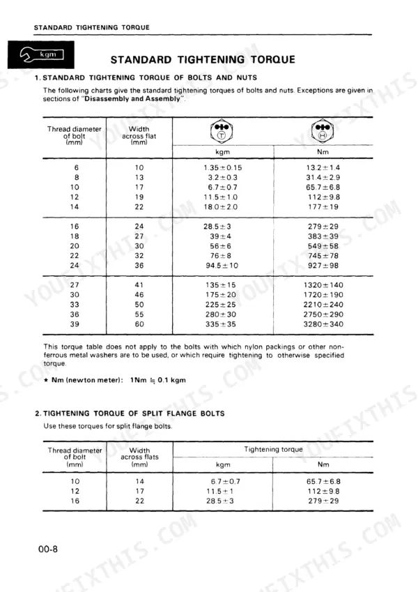
The cylinder head mounting bolts for the PC100-5 must be tightened in three steps. The first step is 7 ± 1 kgm, the second step is 11 ± 0.5 kgm, and the third step is 90 ± 3°. p. 457
What is the standard valve clearance for the intake and exhaust valves on the PC100-5 and PC120-5?
The standard valve clearance for both the intake and exhaust valves on the PC100-5 and PC120-5 is 0.35 mm for the intake valve and 0.50 mm for the exhaust valve. p. 192
What is the capacity of the hydraulic tank for the PC100-5 and PC120-5?
The specified capacity for the hydraulic tank on both the PC100-5 and PC120-5 is 100 liters. p. 459
How quickly can I access this Komatsu PC100-5 manual after buying?
All 644 pages arrive as one searchable PDF at checkout. Read it at the desk, then take the phone out to the machine.
Am I free to print this Komatsu PC100-5 Shop Manual?
Yes. Printing works from any reader and any printer, for your own shop use.


Reviews
There are no reviews yet.