
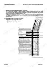
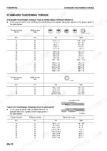
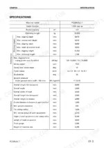
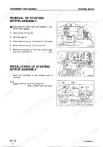
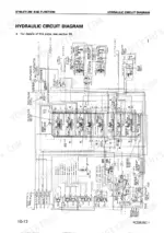
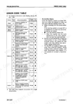
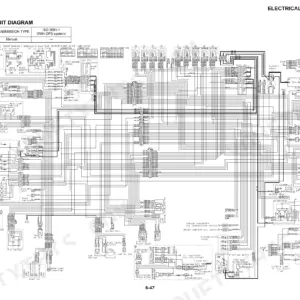
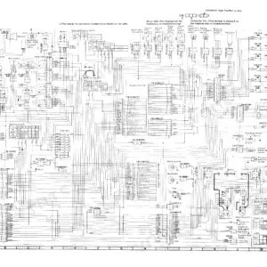
Printed by Komatsu under publication number SEBM015903, this 661-page factory book is the Komatsu PC228US-2, PC228USLC-1, PC228USLC-2 shop manual PDF for the hydraulic excavator. Testing and Adjusting takes up about a third of the pages, with troubleshooting charts and error code tables that trace a fault from the monitor display to the connector pins and the reading expected there. From there, Disassembly and Assembly handles the starting motor, alternator and fuel injection pump, Maintenance Standard sets wear limits for the final drive, swing circle and swing machinery, and full hydraulic and electrical circuit diagrams close the book. Bring the oil to 45 to 55°C before you measure hydraulic pressure, and look for 20 to 30 V at the PPC lock solenoid with the safety lever at FREE. Nobody digs while one reading is missing. Bookmarks split the PDF by section, and the text layer lets you type a connector number and land on the right page in seconds.
What's Inside This Komatsu PC228US-2, PC228USLC-1, PC228USLC-2 Manual
| System | Pages | Key Topics |
|---|---|---|
| General | 27-43 | Specification Dimension Drawings, Specifications, Weight Table |
| Structure and Function | 44-158 | Engine Related Parts, Hydraulic Pump, Control Valve |
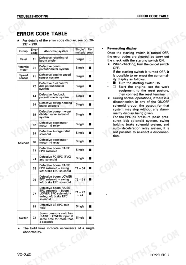
| Testing and Adjusting | 159-385 | Tools for Testing, Adjusting, And Troubleshooting, Measuring Engine Speed, Testing and Adjusting Hydraulic Pressure |
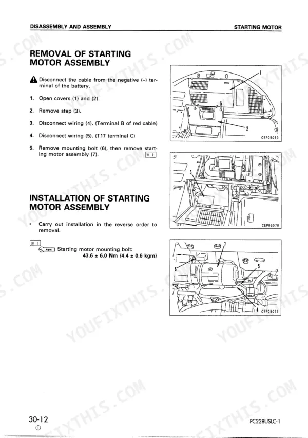
| Disassembly and Assembly | 386-613 | Starting Motor, Alternator, Fuel Injection Pump |
| Maintenance Standard | 614-656 | Final Drive, Swing Circle, Swing Machinery |
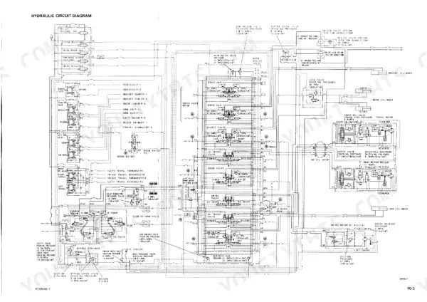
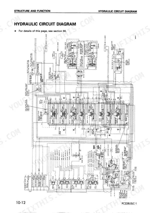
| Others | 657-661 | Hydraulic Circuit Diagram, Electrical Circuit Diagram |
Quick Reference Specifications
| Specification | Value | Page |
|---|---|---|
| PC228USLC-1 | ||
| Starting motor | 24V, 4.5 kW | p. 31 |
| Battery | 12V, 110 Ah × 2 | p. 31 |
| Fuel control dial abnormality detection area | 0 to 0.25 V | p. 136 |
| Boom potentiometer voltage | 0.30 - 0.57 V | p. 174 |
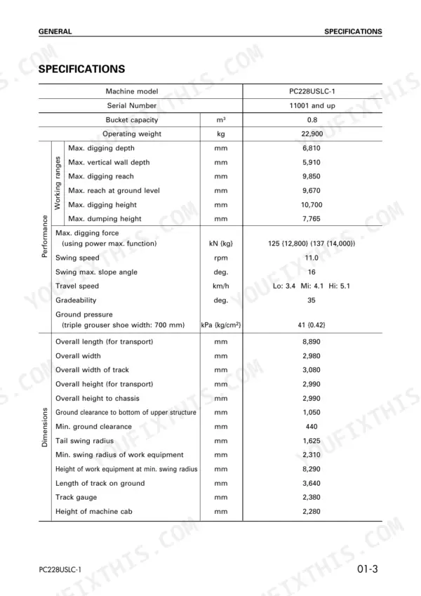
| Operating Weight | 22,900 kg | p. 30 |
| All Models | ||
| Oil temperature when measuring | 45 - 55°C | p. 207 |
| Air bleed plug tightening torque | 17.15 ± 2.45 Nm {1.75 ± 0.25 kgm} | p. 211 |
| Potentiometer input signal voltage (Boom) | 0.31 - 0.57 V | p. 215 |
| Engine Oil Pan Capacity (Specified) | 26.3L | p. 42 |
| Hydraulic Tank Capacity (Specified) | 239L | p. 42 |
| Fuel Tank Capacity (Specified) | 340L | p. 42 |
| Offset boom specification machine | ||
| Potentiometer input signal voltage (Arm) | 0.33 - 1.11 V | p. 215 |
Komatsu PC228US-2, PC228USLC-1, PC228USLC-2 Common Problems This Manual Covers
Komatsu PC228US-2 engine starting performance is poor, starting motor cranks engine slowly and starting always takes time
Check battery electrolyte specific gravity against the charging-rate table on page 273. It must exceed the 70% value, or the 75% value in cold areas. Measure voltage between alternator terminal R and terminal E for 26 to 30 V. Inspect the air cleaner element, fuel filter, strainer and feed pump strainer directly, and clean any that are clogged.
Manual Section: Engine System (S Mode) p. 273Engine does not turn when starting switch is turned to START, pinion does not move out
Check the battery terminals for looseness and low electrolyte, then test specific gravity and voltage. As page 274 directs, turn the starting switch OFF, then connect terminal B and terminal C at the starting switch, the starting motor and the safety relay in turn until the engine starts. Verify 24V between battery relay terminal M and terminal E. Inspect ring gear teeth for chipping.
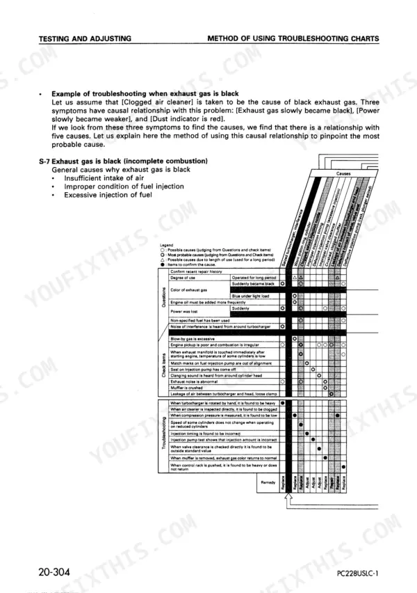
Manual Section: Engine System (S Mode) p. 274Exhaust smoke is black with power slowly becoming weaker and dust indicator showing red
Inspect the air cleaner element directly using the S-7 chart on page 271, and clean it if it is clogged. When smoke and power fade gradually with a red dust indicator, the chart points to that cause first. If the smoke stays black, check for air leakage or a loose clamp between the turbocharger and head, then check the injection nozzles and compression pressure.
Manual Section: Engine System (S Mode) p. 271Electrical system caution lamp flashes with boom potentiometer abnormality and mistaken boom cushion positioning
Measure the boom potentiometer signal voltage between K3 (9) and K2 (9) as described on page 298. A normal reading is 0.31 to 0.57 V. Confirm the related connectors are fully seated before you condemn any part. If you remove the potentiometer assembly from the work equipment, do not shake or rotate its lever unnecessarily (page 225).
Manual Section: Controller, Electrical System (E Mode) p. 298Controller detects abnormality in 2-stage relief solenoid valve system with electrical system caution lamp flashing
Disconnect connector K28. Press the lock stopper down with your thumb and never pull with one hand (page 232). Measure resistance between K28 (male) pins (1) and (2) against 20 to 60 Ω, per page 175. Then check K28 (female) (2) to chassis ground for max. 1 Ω, as shown on page 312.
Manual Section: Controller, Electrical System (E Mode) p. 312Boom RAISE stop EPC solenoid system abnormality with electrical system caution lamp flashing on monitor
Measure Boom RAISE EPC solenoid resistance between K16 and K17 against 5 to 25 Ω, following page 174. Then test the wiring harness between K1 (female) (16) and K17 to chassis for max. 10 Ω on page 314. Never touch connector contacts with your hand, and do not open the control box cover unless you have to (page 235).
Manual Section: Controller, Electrical System (E Mode) p. 314Frequently Asked Questions
How do you release residual hydraulic pressure on a PC228US-2?
To release residual hydraulic pressure, lower the work equipment completely to the ground and stop the engine. Then, loosen the oil filler cap on the hydraulic tank slowly to release the internal pressure. This procedure is detailed on page 190. p. 190
What are the torque specifications for the main relief valve assembly on Komatsu PC228US-2, PC228USLC-1, PC228USLC-2?
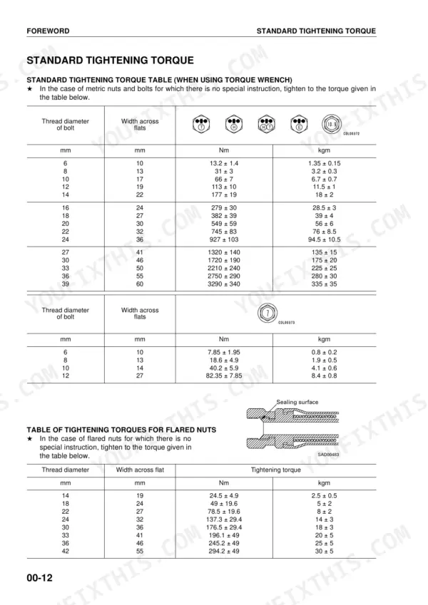
The main relief valve assembly should be tightened to a torque of 54.5 ± 5.0 Nm (5.5 ± 0.5 kgm). p. 547
What is the standard valve clearance for the S6D102-1 engine in the Komatsu PC228US-2, PC228USLC-1, PC228USLC-2?
The standard valve clearance for the intake valve is 0.25 mm and for the exhaust valve is 0.51 mm. p. 161
What is the capacity of the hydraulic tank for the PC228USLC-1?
The specified capacity for the hydraulic tank is 170 liters. p. 523
What is the tightening torque for the cylinder head mounting bolts on the Komatsu PC228US-2, PC228USLC-1, PC228USLC-2?
The cylinder head mounting bolts are tightened in three passes: first to 90.0 ± 5.0 Nm (9.2 ± 0.5 kgm), second to 120.0 ± 5.0 Nm (12.2 ± 0.5 kgm), and third by tightening 90° ± 5°. p. 415
Is this Komatsu PC228US-2 manual a download or a disc?
Instant PDF download. You get the full 661-page searchable Shop Manual immediately after payment. Open it on your laptop, tablet, or phone right in the shop.
Does this Komatsu PC228US-2 manual allow printing?
Yes. Print the pages you need for the job in your own shop, and bin them when they get greasy.

Reviews
There are no reviews yet.