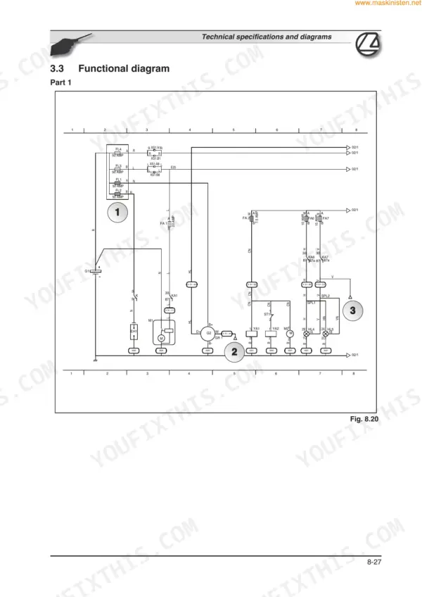
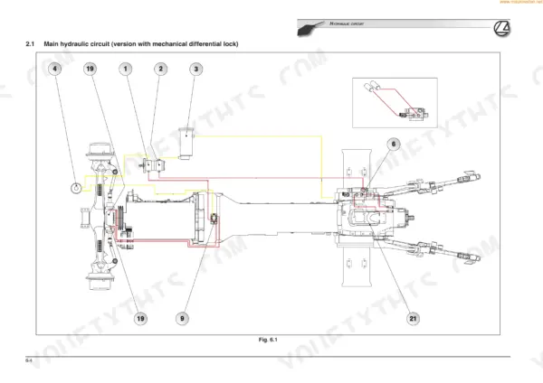
Looking for a reliable Landini 105 training manual pdf? This 534-page factory reference (OEM #4208730M1) breaks down every system for the Globalfarm 95, 105, 90, and 100 tractors, from the front axle to the 24x12 gearbox. Inside, you get detailed wiring diagrams for the dashboard and sensor lines, plus high-flow hydraulic schematics outlining the mechanical differential lock. Open up the mechanical power lift chapters to find step-by-step operating pressure tests, valve system overhauls, and a full set of troubleshooting charts. Swap your engine oil filter every 500 hours and change the dry air filter at the 1000-hour mark to maintain factory performance standards. Your time in the shop is too valuable for forum guesswork. Grab this bookmarked file, pull it up on your laptop or tablet, and get your tractor back to work.
What's Inside This Landini Globalfarm 90–105 & Vision 85 Manual
| System | Pages | Key Topics |
|---|
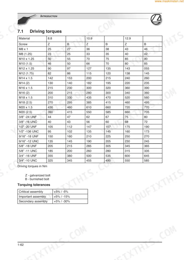
| Introduction | 1-72 | How to Consult the Manual (Introduction, Structure of the Manual), Tractor Identification and Technical Specifications (Weights and Dimensions) |
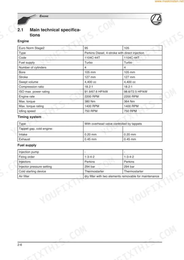
| Engine | 73-94 | Precautions and Safety Recommendations, Technical Specifications (Main Technical Specifications), Driving Torques (Standard Driving Torques, Recommended Driving Torques) |
| Clutch | 95-106 | Precautions and Safety Recommendations (Drawing of the Assembly, Operation), Technical Specifications (Main Technical Specifications), Inspection, Overhaul and Adjustment |
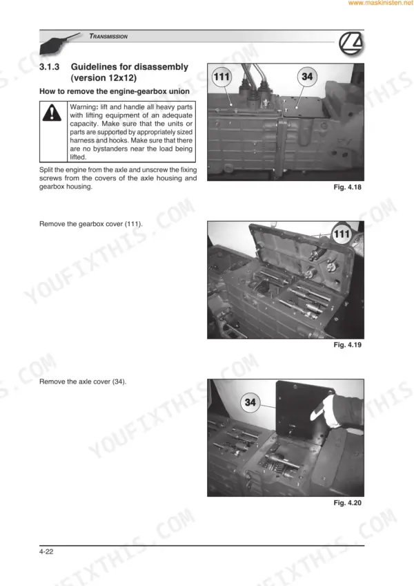
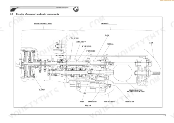
| Transmission | 107-240 | Precautions and Safety Recommendations (Introduction, Assembly Drawings of the Versions, Drawing of Assembly and Main Components, Operation, Control Devices, Technical Specifications, Driving Torques and Sealants) |
| Front Axle | 241-262 | Precautions and Safety Recommendations (Drawing of Assembly and Main Components, 4WD Engagement, Operation), Technical Specifications (Main Technical Specifications) |
| Hydraulics | 263-330 | Precautions and Safety Recommendations (Main Hydraulic Circuit, Description, Functional Diagram, Low Flow Circuit, High Flow Circuit, Lubrication Circuit) |
| Mechanical Power Lift | 331-372 | Precautions and Safety Recommendations (Drawing of Assembly and Main Components, Power Lift Operating Modes, Main Components of the Valve System, Valve System Operating Modes) |
| Electrical System | 373-502 | Precautions and Safety Recommendations (Basic Concepts, Electricity Symbols, How to Read and Interpret a Functional Wiring Diagram) |
| Special Tools | 503-534 | Fri Rex, Cmb Myt a, Cmb Myt B, Cmb Myt C, Cmb Myt D, Cmb Rex a, Cmb Rex B, Cmb Rex |
Quick Reference Specifications
| Specification | Value | Page |
|---|
| Engine oil filter replacement interval | Every 500 hours | p. 31 |
| Fuel filter replacement interval | First two times after every 50 hours (at 50 and 100 hours), then every 500 hours | p. 31 |
| Dry air filter replacement interval | Every 1000 hours service or once a year | p. 31 |
| Oil cleaning by means of | 1 - Wire mesh filter on pump intake pipe
2 - Replaceable cartridge filter on the engine delivery side. | p. 79 |
| Air filter | dry filter with two elements removable for maintenance | p. 78 |
| Retainer screw on DP210 fuel injection pump shaft | 17 Nm | p. 84 |
| Type of connection | With open center and "Push-Pull" quick couplings | p. 282 |
| Calibration valve pressure | 170 bar | p. 283 |
| Three-point hitch control knob | move knob (B) fully back on the sector | p. 337 |
| Engine oil pressure switch sensor | The sensor (SP3) on the left-hand side of the engine, indicates when the engine oil pressure is too low by means of an indicator light on the instrument. | p. 410 |
| Engine coolant temperature sensor | This sensor (ST2) installed on the cylinder head, indicates the operating temperature of the engine and any overheating through an analog signal on the instrument. | p. 411 |