
The factory workshop manual for seven Liebherr excavators of one family - wheeled A 308, A 310B, A 312 and A 316, plus crawler R 308, R 310B and R 312.
Nineteen repair groups bound from three volumes cover the engine (BF 4 M 1011 F / BF 4 M 2011), splitterbox, hydraulic pumps and components, swing gear and swing ring, two speed travel gearbox, axles, steering, oscillating axle stabilizer, brakes, cab and heater.
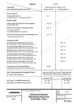
You get electrical circuit diagrams, the full hydraulic circuit diagram, and the pressure values that actually matter on these machines: 320-10 bar operating, 32+/-1 bar servo on the R 312. Text runs trilingual German/English/French. It is a scan with no text layer, but real PDF bookmarks jump you straight to each group.
What's Inside This Liebherr A308 to R312 Manual
| System | Pages | Key Topics |
|---|---|---|
| Index and Front Matter | 1-16 | Machine Index, Group Overview, Swing Gear and Brake, Travel Gear, Two Speed Gear Box References |
| Group 1 - General Information | 17-58 | Safety, Machine Identification, Service Instructions |
| Group 2 - Tools | 59-154 | LMS-Litronic Measuring System, Sensors, Accessories |
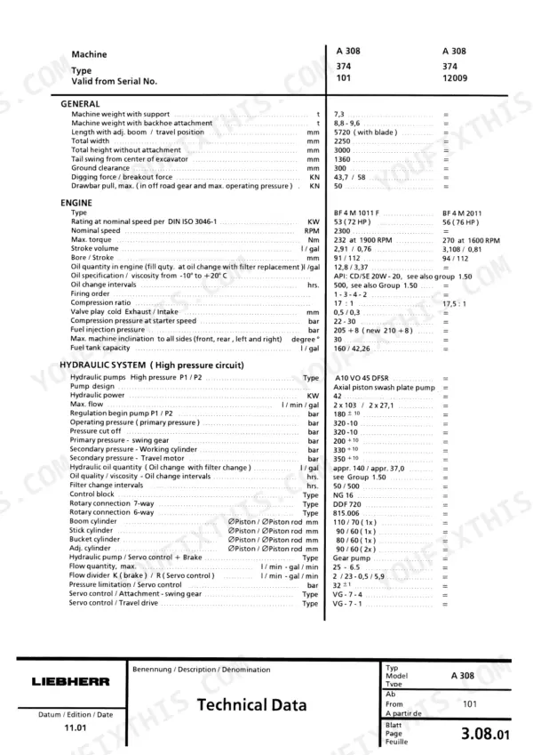
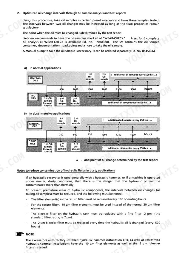
| Group 3 - Technical Data / Maintenance Guidelines | 155-196 | Technical Data Tables per Model, Maintenance Guidelines, Oil Change Intervals, Oil Sample Analysis, Filter Requirements |
| Group 4 - Engine | 197-218 | Operating Values, Performance Data, Adjustment Values, Fill Quantities, Injection Valves, Filter Elements, Safety Devices, Screw Torque Values |
| Group 5 - Clutch / Splitterbox | 219-228 | Elastic Coupling Task and Construction, Function, Removal, Installation |
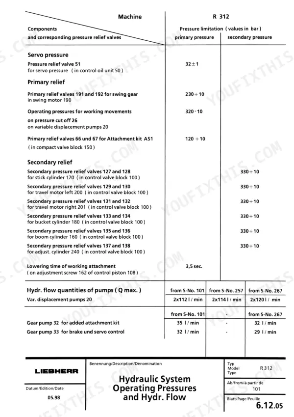
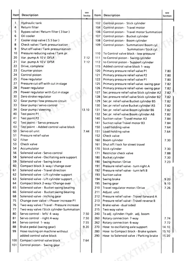
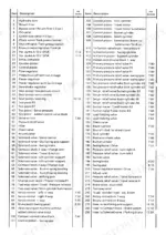
| Group 6 - Hydraulic System | 229-328 | Hydraulic Circuit Diagram, Component Legend, Operating Pressures, Pressure Limitation Tables, Pump Flow Quantities |
| Group 7 - Hydraulic Components | 329-636 | Variable Displacement Pumps A10 VO 45 DFSR, Control Valve Blocks, Pressure Relief Valves, Servo Control, Cylinders |
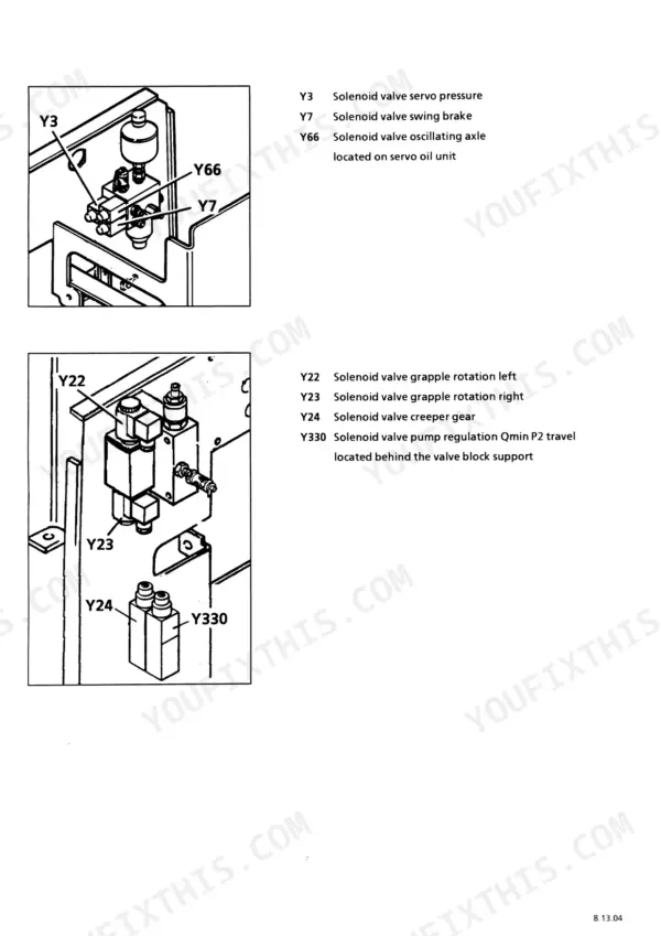
| Group 8 - Electrical System | 637-1106 | Circuit Diagrams, Component Locations, Solenoid Valves, Relays and Fuses, Connectors |
| Group 9 - Swing Gear / Swing Brake | 1107-1146 | Design, Function, Power Flow, Lubrication System, Maintenance, General Data |
| Group 10 - Swing Ring | 1147-1156 | Design, Function, General Data |
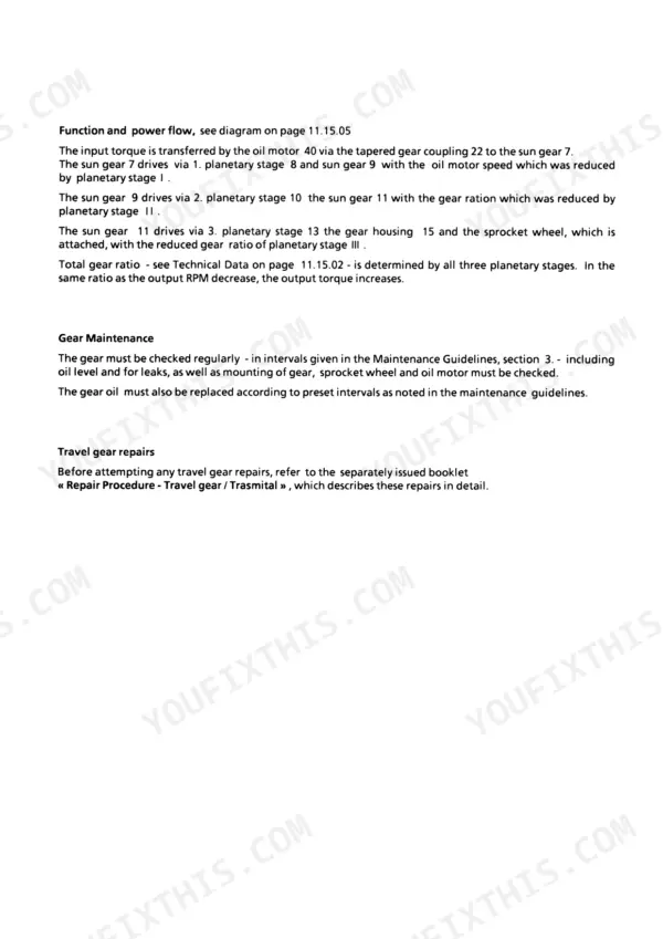
| Group 11 - Final Drive Gear / Two Speed Gear Box | 1157-1334 | Travel Gear Construction, Function and Power Flow, Maintenance, Repairs, General Data, Installation Values |
| Group 12 - Track Components / Axles | 1335-1526 | Chain, Track Pad, Track Pad Bolts, Track Roller, Carrier Roller Specifications |
| Group 13 - Steering | 1527-1634 | Steering System Design, Steering System Function, Pressure Checks and Adjustments |
| Group 14 - Oscillating Axle Stabilizer | 1635-1660 | Use and System Design, Rotary Connection 252, Solenoid Valve 58, Pressure Switch S 58, Function, Bleeding the System |
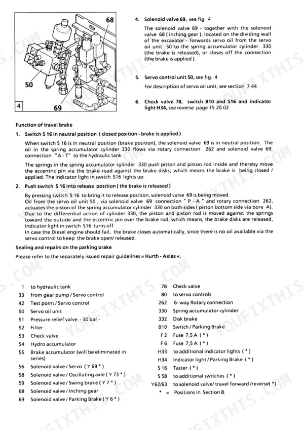
| Group 15 - Brake System | 1661-1688 | Gear Pump 33, Accumulator Charge Valve, Compact Brake Block, Operating Brake System, Accumulators |
| Group 16 - Special Attachments / Additional Hydr. Install. | 1689-1942 | Attachment Installation Kits, Overload Warning Device, Adjustment Guidelines |
| Group 17 - Cab / Heater Air Conditioning System | 1943-1960 | Technical Data, Design and Function, Cooling Circuit Schematic, Electrical Schematic, Air Conditioning Operation, Maintenance and Troubleshooting |
| Group 18 - Under - / Uppercarriage Attachments | 1961-1972 | Maintenance Free Bearings in the Attachment Area, Expander Pins |
| Group 19 - Arrangement of Tanks | 1973-1984 | Hydraulic Tank Design and Function, Fuel Tank |
Quick Reference Specifications
| Specification | Value | Page |
|---|---|---|
| Engine Type (A 308) | BF 4 M 1011 F | p. 157 |
| Engine Type (A 308, alternative) | BF 4 M 2011 | p. 157 |
| Rated Power (BF 4 M 1011 F) | 53 kW (72 HP) | p. 157 |
| Rated Power (BF 4 M 2011) | 56 kW (76 HP) | p. 157 |
| Nominal Speed | 2300 rpm | p. 157 |
| Max. Torque (BF 4 M 1011 F) | 232 Nm at 1900 rpm | p. 157 |
| Max. Torque (BF 4 M 2011) | 270 Nm at 1600 rpm | p. 157 |
| Bore / Stroke | 91 / 112 mm | p. 157 |
| Compression Ratio | 17 : 1 | p. 157 |
| Firing Order | 1 - 3 - 4 - 2 | p. 157 |
| Machine Weight with Support (A 308) | 7,3 t | p. 157 |
| Digging / Breakout Force (A 308) | 43,7 / 58 kN | p. 157 |
| Hydraulic Pump | A10 VO 45 DFSR axial piston swash plate | p. 157 |
| Hydraulic Power | 42 kW | p. 157 |
| Max. Pump Flow (A 308) | 2 x 10³ l/min | p. 157 |
| Operating Pressure | 320 -10 bar | p. 157 |
| Secondary Pressure - Working Cylinder | 330 +10 bar | p. 157 |
| Secondary Pressure - Travel Motor | 350 +10 bar | p. 157 |
| Servo Pressure | 32 +/-1 bar | p. 157 |
| Engine Oil Quantity (A 308) | 12,8 l | p. 157 |
Liebherr A308 to R312 Common Problems This Manual Covers
Machine will not travel in reverse, forward works fine (a known A 310B complaint, usually a stuck travel spool or pressure not reaching the reverse side)
Start with the servo circuit, not a teardown. Check servo pressure against the 32+/-1 bar test value, then trace the reverse travel line on the full hydraulic circuit diagram to isolate whether the pilot signal or the main spool is at fault before stripping the control valve per Group 6.
Manual Section: Group 6 - Hydraulic System p. 245Bucket curl or dump moves at a crawl unless you feather another function at the same time
That pattern points at flow starvation or the pump regulator, not the cylinder. Run the pressure and flow checks against rated output (2 x 10³ l/min on the A 308), verify operating pressure holds 320-10 bar under load, then work through the A10 VO 45 DFSR pump and regulator procedures in Group 7 before condemning anything.
Manual Section: Group 7 - Hydraulic Components p. 157Play, rumbling or uneven motion in the swing bearing, a stocked wear item across the whole R 308 / R 310B / R 312 / A 308 / A 312 range
Check grease condition and bearing play before it chews itself up, because a collapsed ring can crack the swing base. Group 10 covers swing ring inspection, removal and installation, and Group 9 handles the swing gear and swing brake you will have off the machine at the same time anyway.
Manual Section: Group 10 - Swing Ring p. 1147Weak or erratic hydraulics across all functions, machine feels tired everywhere at once
Do not start by pulling the pump. Work the cheap end first: suction line and filters, then measure servo, operating and secondary pressures against the test value tables in Group 3, adjusting the pressure cut off and secondary valves per procedure. Most tired machine complaints resolve at a relief valve, not inside the pump.
Manual Section: Group 3 - Technical Data / Maintenance Guidelines p. 155Frequently Asked Questions
There is no diagnostic port on my A 310B. How does this manual expect me to find a hydraulic fault?
The old fashioned way, and it works. These machines predate onboard electronics, so there is no fault code chapter because the machines have no fault codes. Diagnosis is done with pressure gauges and the hydraulic circuit diagram. The book gives you the test values to check against: servo pressure 32+/-1 bar, swing primary 200+10 bar (230+10 on R 312), operating pressure 320-10 bar, secondary 330+10 bar on the working cylinders and 350+10 bar on the travel motor. Gauge reads wrong, you follow the circuit to the component. Bring test hoses. p. 157
Does it cover the hydraulic pump? Mine died around 4700 hours and I hear that is not rare.
Yes. The A10 VO 45 DFSR axial piston swash plate pump gets its own treatment in Group 7 - Hydraulic Components, with the regulator covered as part of the pump. The technical data lists rated flow (2 x 10³ l/min on the A 308) and, for the R 312, flow by serial number: 2 x 112 l/min from serial 101, 2 x 114 from 257, 2 x 120 from 267. That serial breakdown matters when you are verifying output on a replacement or reman pump. p. 329
Is this only for the wheeled A machines, or does it cover the crawlers too?
Both. The A 308, A 310B, A 312 and A 316 wheeled machines share this book with the R 308, R 310B and R 312 crawlers. Shared groups (engine, hydraulics, swing gear, electrics) apply across the range, while Group 12 splits into track components for the R machines and axles for the A machines, and Groups 13, 14 and 15 handle steering, the oscillating axle stabilizer and the brake system on the wheeled units. p. 945
What engine information is in here?
Group 4 covers the diesels fitted to this range, listed by type code: BF 4 M 1011 F at 53 kW (72 HP) and BF 4 M 2011 at 56 kW (76 HP), both at 2300 rpm nominal. The data tables give max torque (232 Nm at 1900 rpm or 270 Nm at 1600 rpm), bore/stroke, compression ratios of 17:1 or 17,5:1, firing order 1-3-4-2, and service capacities: 12,8 l engine oil, around 140 l hydraulic oil, 160 l fuel. p. 157
Is the PDF searchable, and what language is it in?
It is a scan of the paper book with no text layer, so text search will not find anything. What saves it: the PDF has real bookmarks mirroring all 19 repair groups, so you click straight to Hydraulic Components or Swing Ring instead of scrolling. Pages run trilingual German/English/French side by side. Individual sheets carry revision dates from 12.91 through 09.99, and the edition reflects factory update no. 8 dated 11.02.02, so late production changes are in. p. 17


Reviews
There are no reviews yet.