
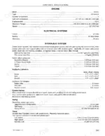
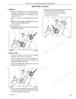
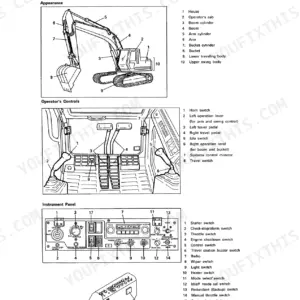
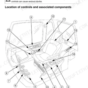
Book No. 2101, the Link-Belt 210 X2 operator manual PDF, settles in 150 pages what no other source can for this hydraulic excavator: what each monitor message means, which pattern the levers are set to, and what the machine lifts at a given reach. Daily inspections, the lubrication chart, and fluid capacities for the engine, swing reduction gear, and travel reduction gears fill most of the book, followed by tracks, rollers and idlers, cylinder leakage checks, and bucket replacement. Earlier chapters walk you through the instrument panel, the anti-theft device, and the control pattern selector valve, while the specifications close with digging force, working range, and lifting capacities. Change the fuel pre-filter every 250 hours; the engine oil filter and main fuel filter go at 500, the pilot oil filter at 2,000. A filter change stalls over one missing interval. Bookmarks and a text layer land you on the capacities table or lift chart in seconds.
What's Inside This Link-Belt 210 X2 Operator Manual
| System | Pages | Key Topics |
|---|---|---|
| General Information | 7-12 | To the Owner, Excavator Components, Identification Numbers |
| Safety, Decals, and Hand Signals | 13-30 | Safety Rules, Safety Area, Utility Safety |
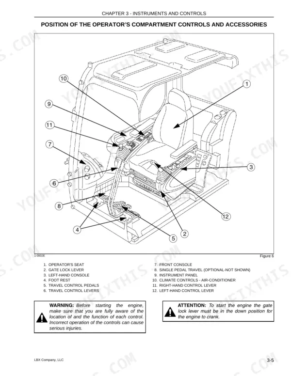
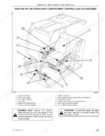
| Instruments and Controls | 31-62 | Cab, Steps and Access Handles, Position of the Operator’s Compartment Controls and Accessories, Operator’s Seat, Seat Controls, Right-Hand Control Arm and Instrument Panel |
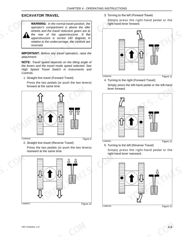
| Operating Instructions | 63-82 | Before Operating the Excavator, Operating the Excavator, Run-In Period, Starting the Engine, Bringing the Excavator Up to Operating Temperature, Engine Operation |
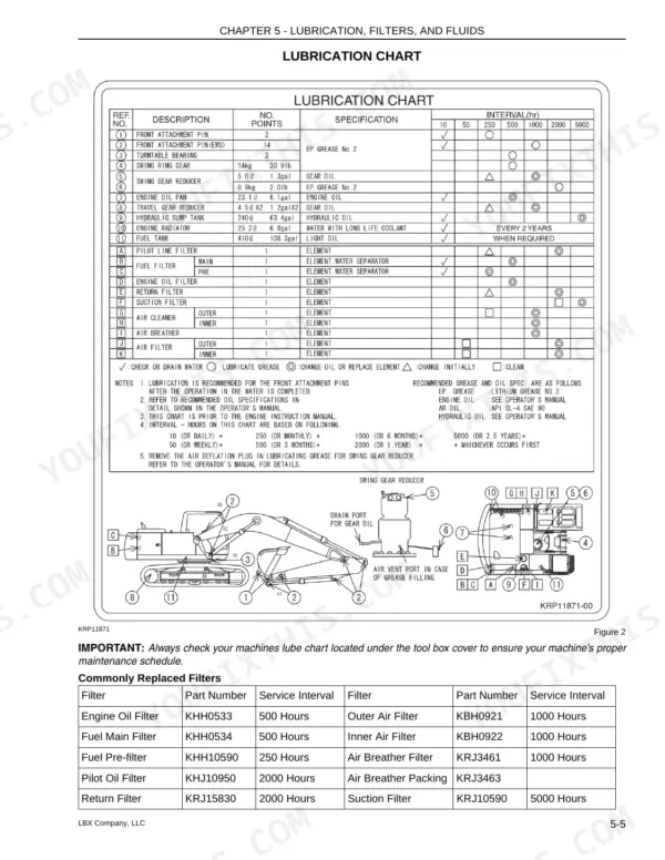
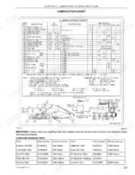
| Lubrication, Filters, and Fluids | 83-116 | Servicing Instructions, Daily Inspections, Lubrication Chart, Air Filter, Radiator |
| Maintenance and Adjustments - General Maintenance | 117-130 | Tracks, Track Rollers, Cylinder Leakage, Bucket Replacement |
| Electrical | 131-138 | Fuses, Battery, Alternator, Starter Motor, Bulb Replacement |
| Specifications: Overview | 139-140 | |
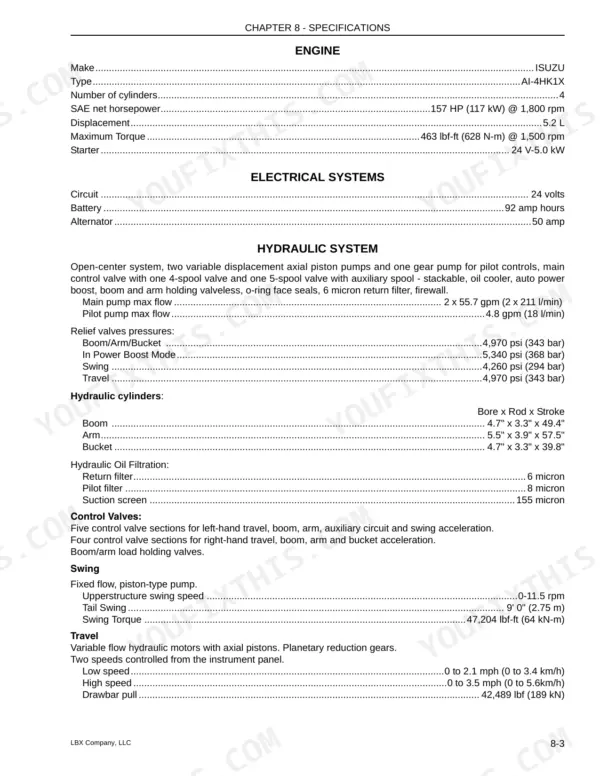
| Specifications | 141-148 | Engine Specifications, Electrical Systems, Hydraulic System, Digging Force, Lifting Capacities |
| Index | 149-150 |
Quick Reference Specifications
| Specification | Value | Page |
|---|---|---|
| Engine Oil Filter Service Interval | 500 Hours | p. 87 |
| Fuel Main Filter Service Interval | 500 Hours | p. 87 |
| Outer Air Filter Service Interval | 1000 Hours | p. 87 |
| Inner Air Filter Service Interval | 1000 Hours | p. 87 |
| Pilot Oil Filter Service Interval | 2000 Hours | p. 87 |
| Return Filter Service Interval | 2000 Hours | p. 87 |
| Travel reduction gear torque | 267-312 Nm | p. 129 |
| Drive sprocket torque | 267-312 Nm | p. 129 |
| Boom/Arm/Bucket relief valve pressure | 4,970 psi (343 bar) | p. 141 |
| In Power Boost Mode relief valve pressure | 5,340 psi (368 bar) | p. 141 |
| Return filter filtration | 6 micron | p. 141 |
| Pilot filter filtration | 8 micron | p. 141 |
Link-Belt 210 X2 Common Problems This Manual Covers
Link-Belt 210 X2 undercarriage track tension too loose with tracks visibly sagging below the frame
Check track tension on both tracks following the procedure on page 120. Measure the slack and adjust until it sits between 11.0 and 11.8 in (280 to 300 mm). Don't guess by eye; a tape measure on the sag tells you more than a walkaround ever will.
Manual Section: Track Tension Troubleshooting p. 120Radiator coolant looking dirty or running low when checking the cooling system at service
Drain the cooling system, rinse it and fill it following the procedure on page 97. Refill to the full cooling system capacity of 6.8 gal (25.6 liters) so you know the whole volume went back in. Inspect the radiator while the system is drained.
Manual Section: Cooling System Troubleshooting p. 97Water collecting in the fuel filters or air trapped in the fuel system after filter service
Drain water from the fuel filters and bleed air from the fuel system using the Fuel System procedures in the maintenance section. Check filter hours against the schedule on page 87: replace the fuel pre-filter every 250 hours and the main fuel filter every 500 hours. Don't skip the bleed after a filter change.
Manual Section: Fuel System TroubleshootingAir trapped in hydraulic components after component service or a hydraulic filter change
Release hydraulic pressure before you open anything, then bleed air from the affected components following the Hydraulic System procedures on page 105. Replace the pilot filter (8 micron) and return filter (6 micron) at 2000 hours per the schedule on page 87. Never crack a fitting on a pressurized circuit.
Manual Section: Hydraulic System Troubleshooting p. 105Hydraulic cylinder leakage suspected from the appearance of the cylinder rod at inspection
Use the Checking for Cylinder Leakage procedure in Chapter 6, Maintenance and Adjustments (page 124). Compare what you see on the rod against the Rod Appearance descriptions there. Inspect each cylinder separately, and release hydraulic pressure before you put your hands near any line or fitting.
Manual Section: Cylinder Leakage TroubleshootingWeak battery or blown fuse in the electrical system with the engine failing to crank
Check the fuses and replace any blown fuse following the Electrical procedures that start on page 117. Inspect the batteries using the battery maintenance steps, and connect a booster battery only by the booster battery connection procedure. Verify that replacement batteries match the 92 amp hour rating and that the alternator is rated 50 amp, both listed on page 141.
Manual Section: Electrical System Troubleshooting p. 117Frequently Asked Questions
What are the hydraulic relief-valve settings for a Link-Belt 210 X2?
The relief valve pressure settings for the Link-Belt 210 X2 are 4,970 psi (343 bar) for the Boom, Arm, and Bucket, 5,340 psi (368 bar) in Power Boost Mode, 4,260 psi (294 bar) for the Swing, and 4,970 psi (343 bar) for Travel. p. 141
What are the replacement specs for the engine oil and fuel filters on the Link-Belt 210 X2?
The Engine Oil Filter (KHH0533) and Fuel Main Filter (KHH0534) have a service interval of 500 hours. The Fuel Pre-filter (KHH10590) has a service interval of 250 hours. p. 87
What are the replacement specifications for the air cleaner filter elements on a Link-Belt 210 X2?
The Outer Air Filter (KBH0921) and Inner Air Filter (KBH0922) have a service interval of 1000 hours. The outer element should be inspected and cleaned every 250 hours or when indicated on the monitor. p. 87
What is the correct track tension for the Link-Belt 210 X2?
The correct track tension for the Link-Belt 210 X2 is 11.0 to 11.8 inches (280-300 mm) of slack measured between the base of the undercarriage and the upper part of the track tread. p. 120
What is the tightening torque for the track shoe bolts on the Link-Belt 210 X2?
The track shoe bolts should be tightened to 67.4 lbf (300 Nm) and then turned an additional 120 degrees. p. 120
How quickly can I access this Link-Belt 210 X2 manual after buying?
This is a 150-page searchable PDF ready for immediate download. Works on any device, so pull it up on your phone while you're under the hood. No shipping, no waiting.
Is printing allowed for this Link-Belt 210 X2 Operator Manual?
Yes. Many buyers print one chapter at a time for their own shop and keep the rest on a tablet.


Reviews
There are no reviews yet.