
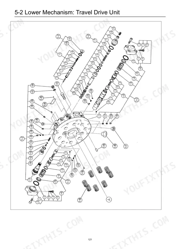
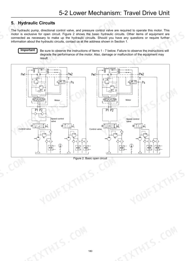
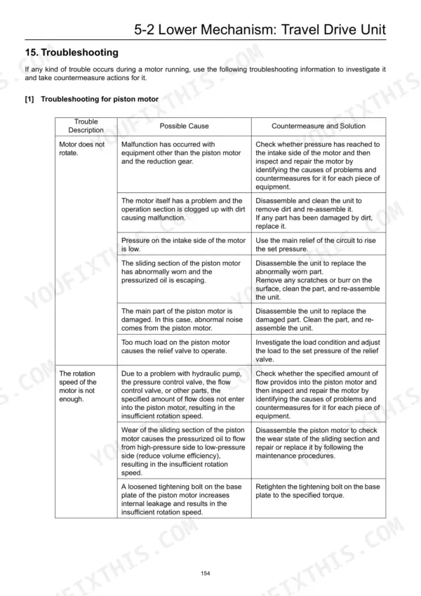
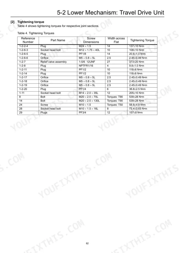
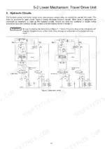
Written for both the 210 X2 and 240 X2 hydraulic excavators, this 550-page Link-Belt 210 X2, 240 X2 shop manual PDF runs from engine consumables through the undercarriage, swing body, pump and valves, attachment and cab. Roughly a third of the book goes to the lower mechanism: travel motor removal and full teardown, plus take-up, carrier and track roller rebuilds. Where the two models part ways, the swing motor and swing reduction gear get separate disassembly procedures for each, while hydraulic schematics and a regulator operation section show how the pump answers your pilot control circuit. Hold travel motor drain pressure to 0.2 MPa in normal use, and torque the relief valve assembly to 373 ± 20 N•m when it goes back in. Guess that figure and you pay for a second teardown. Bookmarked, text-searchable pages put the right procedure in front of you quickly, so your excavator is digging again by the next shift.
What's Inside This Link-Belt 210 X2, 240 X2 Manual
| System | Pages | Key Topics |
|---|---|---|
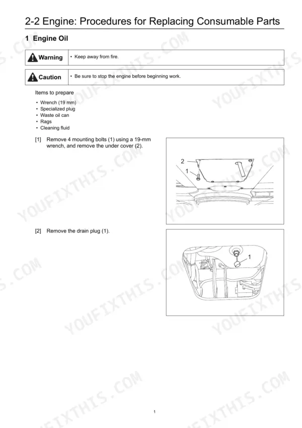
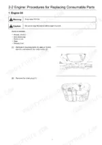
| Engine | 5-58 | Procedures for Replacing Consumable Parts (Engine Oil, Removal and Installation of Engine Oil Element, Fuel Filter, Charge Fuel Pump Filter, Removal and Installation of Fan Belt, Removal and Installation of Air Conditioner Belt) |
| Air Conditioner | 59-60 | Compressor, Condenser, Receiver Dryer |
| Maintenance | 61-62 | Electric Equipment Checking Procedure (Voltage Measurement Procedure) |
| Lower Mechanism | 63-236 | Track Shoe, Travel Drive Unit, Take-Up Roller, Upper Roller, Lower Roller |
| Swing Body | 237-349 | Swing Driving Unit, Swing Motor, Swing Reduction Gear, Center Joint, Counterweight |
| Upper Swing Body: Pump and Valves | 350-461 | Pump, Regulator, Remote Control Valve, Control Valve, Solenoid Valve, Cushion Valve |
| Upper Swing Body: Cooling and Tank | 462-485 | Radiator, Oil Cooler, Hydraulic Oil Tank, Fuel Tank |
| Structure: Attachment | 486-513 | Bucket, Bucket Link, Bucket Cylinder, Arm, Arm Cylinder, Boom, Boom Cylinder, HBCV |
| Light and Cab | 514-536 | Boom Light, Tool Box Light, Cab Assembly, Operator's Seat, Wiper, Monitor, Window Lock |
| Hydraulic Equipment and Others | 537-550 | Accumulator, Suction Filter, Return Filter, Pilot Filter, Side Door, Draining Oil |
Quick Reference Specifications
| Specification | Value | Page |
|---|---|---|
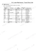
| Plug (1-2-2-4) Tightening Torque | 137 ± 10 N•m | p. 86 |
| Socket head bolt (1-2-6-3) Tightening Torque | 108 ± 10 N•m | p. 86 |
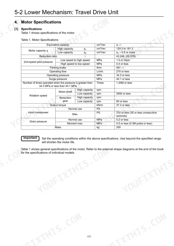
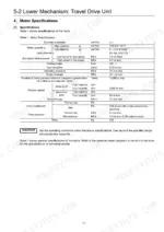
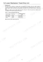
| Drain pressure tolerance range (Normal use) | 0.2 MPa max. | p. 139 |
| Drain pressure tolerance range (Instant maximum) | 0.5 MPa max. | p. 139 |
| Shoe sliding surface roughness | 0.8 S | p. 101 |
| Cam plate (5) surface roughness | 0.8 S | p. 101 |
| Piston to cylinder bore clearance (D-d) for K3V63, K5V80 | 0.028 / 0.056 mm | p. 368 |
| Piston to cylinder bore clearance (D-d) for K3V112 | 0.039 / 0.067 mm | p. 368 |
| Travel Motor Drain Pressure (Normal use) | 0.2 MPa max. | p. 139 |
| Travel Motor Drain Pressure (Instant maximum) | 0.5 MPa max. | p. 139 |
| Travel Motor Operating Pressure | 34.3 MPa or less | p. 181 |
| Travel Motor Surge Pressure | 44.1 MPa or less | p. 181 |
Link-Belt 210 X2, 240 X2 Common Problems This Manual Covers
Link-Belt 210 X2 and 240 X2 travel motor does not rotate, speed insufficient, or rotation fluctuates
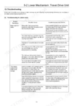
Measure travel motor drain pressure before pulling anything apart. Compare the reading against 0.2 MPa max in normal use and 0.5 MPa instant maximum, per page 139. Then work through the piston motor troubleshooting chart for no rotation, low speed, and fluctuation, and inspect the motor housing and ports for oil leaks.
Manual Section: Lower Mechanism p. 139Travel motor relief valve problem: motor does not stop or gives big shock when stopping
Check the relief valve against the troubleshooting chart, which separates no rotation, slow rotation, failure to stop, and stopping shock. Compare measured operating pressure with the 34.3 MPa or less rating on page 181. When reinstalling the relief valve assembly, torque it to 373 ± 20 N·m per page 86.
Manual Section: Relief Valve TroubleshootingTravel motor counter balance valve: motor does not stop or rotation fluctuates with external load
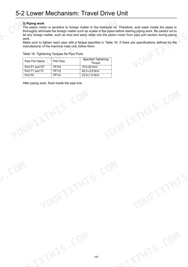
Inspect the counter balance valve following the troubleshooting steps. Confirm whether the motor fails to rotate, runs slow, will not stop, or fluctuates when an external load drives it. When you reconnect travel motor ports P1 and P2, torque them to 372 ± 20 N·m per page 147.
Manual Section: Counter Balance Valve TroubleshootingTravel drive reduction gear making abnormal noise, running abnormally hot, or leaking oil
Check the reduction gear lubricating oil before anything else. Drain it, look for metal and a burnt smell, and refill to the 3.5 L capacity listed on page 135. Then work the reduction gear troubleshooting chart for no rotation, abnormal noise, overheating, and oil leaks, checking the housing for the leak source.
Manual Section: Lower Mechanism p. 135Swing motor shows excessive slippage, insufficient torque, abnormal sounds, abnormal heating, or oil leakage
Inspect the swing motor using the Swing Motor troubleshooting chart in the Swing Body section, matching slippage, low torque, noise, heat, or leakage to its listed cause. If the motor has to come off, rig for its 71 kg weight listed on page 288 before lifting it out of the upper structure.
Manual Section: Swing Body p. 288Remote control valve in the pilot circuit: secondary pressure reads low, unstable, or too high
Test remote control valve secondary pressure and note whether it reads low, unstable, or too high; the Remote Control Valve troubleshooting chart in the Pump and Valves section treats each condition separately. Before opening the valve, check the pilot filter in the Hydraulic Equipment and Others section starting on page 537.
Manual Section: Remote Control Valve TroubleshootingFrequently Asked Questions
What are the engine oil element replacement specs for the Link-Belt 210 X2, 240 X2 excavator?
The engine oil element is replaced using a specialized wrench. The procedure is found on page 7 of the manual. p. 7
What is the tightening torque for the M20 bolt on the Link-Belt 210 X2/240 X2 travel drive unit?
The tightening torque for the M20 x 2.0 x 70L bolt (Reference number 8) on the travel drive unit is 539±28 N•m. p. 86
How often should the hydraulic oil be replaced in the travel drive unit?
The initial replacement of hydraulic oil in the travel drive unit should be performed after 500 hours of operation. Subsequent routine checks and replacements should be performed at an interval of around 500 hours. p. 153
What is the specified tightening torque for the Link-Belt 210 X2/240 X2 4-way selector valve installation bolts?
The 4-way selector valve installation bolts (M12 x 30) should be tightened to a torque of 103 N•m. p. 253
What is the required oil volume for the Link-Belt 210 X2/240 X2 swing reduction gear?
The swing reduction gear requires approximately 9.7 liters of gear oil. p. 346
Will this Link-Belt 210 X2 Shop Manual download right away?
This is a 550-page searchable PDF ready for immediate download. Works on any device, so pull it up on your phone while you're under the hood. No shipping, no waiting.
Can I print this Link-Belt 210 X2 manual?
You can. Print the sections you want for your own use and keep the file as your backup.


Reviews
There are no reviews yet.