
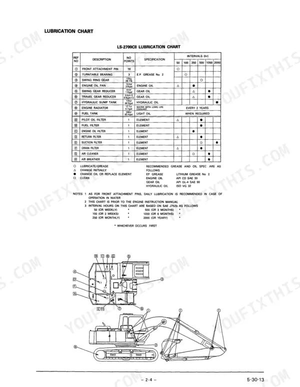
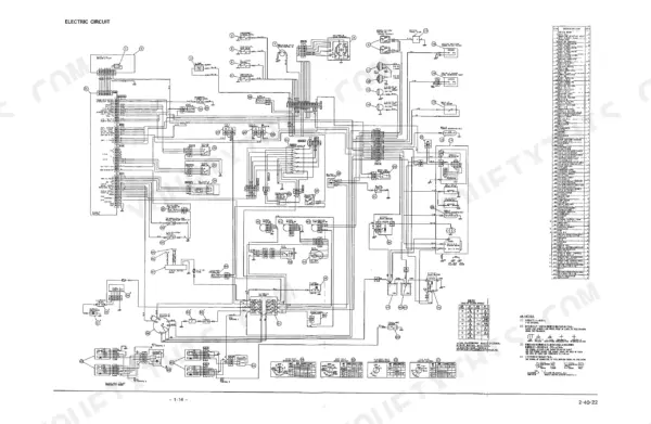
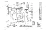
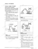
Within the hour you'll be greasing the LS-2700's pins against its lubrication chart and ticking down the inspection check list, and this Link-Belt LS-2700 operator manual PDF (Book No. WDL2700-1E, 106 pages) is the copy written for that LS-series hydraulic excavator. Hydraulic system and electric circuit diagrams open the operation section, followed by the instruments and controls, operation modes, one touch idle, and the emergency bypass for a failed switch. Inspection and maintenance takes up more than a third of the book, running through periodic and irregular service, troubleshooting, and fuel and lubricant grades by ambient temperature; the book then closes on selecting and installing a hydraulic hammer. Replace the hydraulic return filter element every 500 hours and the suction filter element every 2,000. Every hour parked is a crew on the clock. Bookmarked and text-searchable, your copy rides in the service truck or the cab, wherever the LS-2700 is digging.
What's Inside This Link-Belt LS-2700 Operator Manual
| System | Pages | Key Topics |
|---|---|---|
| Preface | 3 | Hydraulic Excavator, Technical Design, Operating Methods, Maintenance Procedures, Engine Manual |
| Caution | 4-6 | Construction Equipment, Operator Training, Maintenance Procedures, Distributor Contact, Equipment Modifications, Safety Labels |
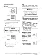
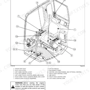
| Operation | 7-44 | Safety, Location of Components, Hydraulic System, Electric Circuit, Instruments and Controls, Operation Modes, One Touch Idle and Switch Operation |
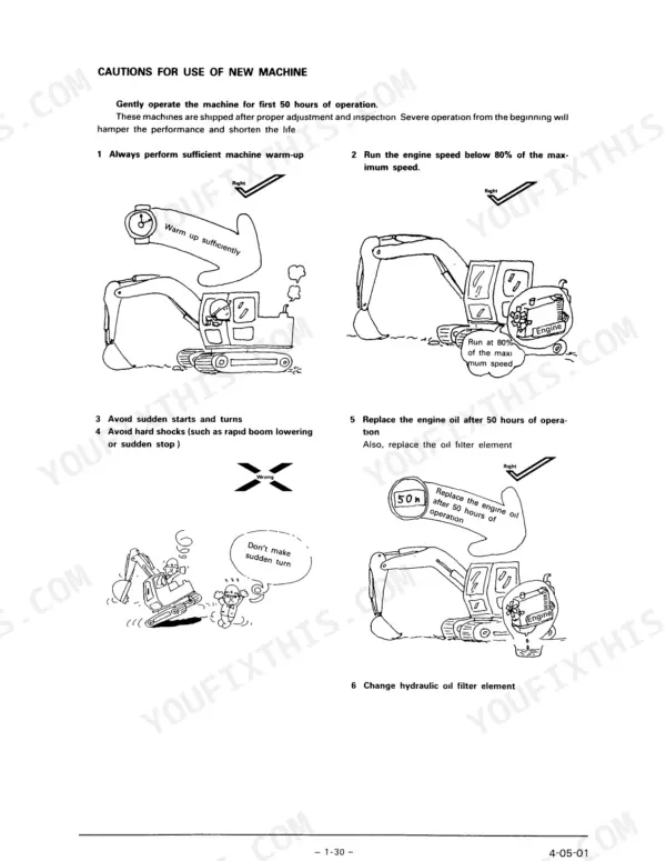
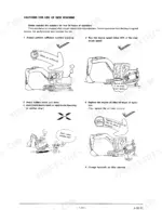
| Operating Instructions | 45-62 | Cautions for Use of New Machine, Engine, Warm Up Operation, Cautions for Operation, Operations, Pulling Out From Soft Ground, Bucket Play, Turning Over and Replacement of Bucket |
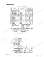
| Inspection and Maintenance | 63-100 | Caution for Inspection, Lubrication Chart, Maintenance Check List, Periodic Maintenance, Irregular Maintenance, Inspections, Measuring Pressure, Troubleshooting |
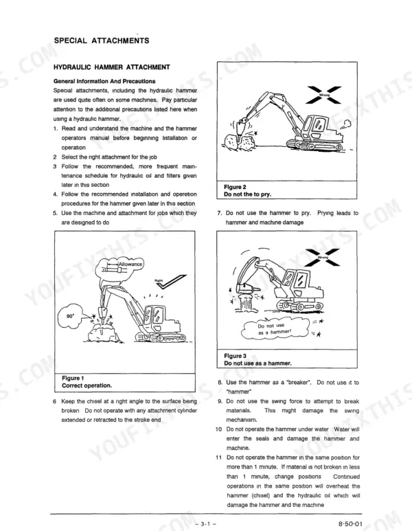
| Special Attachment | 101-106 | Hydraulic Hammer Attachment (Selection of the Hammer Attachment, Installation of the Hammer Attachment, Control of the Hydraulic Oil Flow and Pressure), Hydraulic Oil Maintenance |
Quick Reference Specifications
| Specification | Value | Page |
|---|---|---|
| Vacuum switch (air filter) | 24V 3.5W | p. 23 |
| Hydraulic return filter element replacement interval | 500 hours | p. 97 |
| Pilot Circuit Setting pressure | 569~650 psi (40~45 kgf/cm²) | p. 89 |
| Travel circuit Setting pressure value | 4,200~4,500 psi (300~5 kgf/cm²) | p. 90 |
| Take-up Roller Oil Capacity | 170cc | p. 69 |
| Upper Roller Oil Capacity | 100-110cc | p. 69 |
| Lower Roller Oil Capacity | 190cc | p. 69 |
| Turntable bearing mounting bolt torque | 384-434 ft-lb | p. 77 |
| Swing reduction gear mounting bolt torque | 384-434 ft-lb | p. 77 |
| Counterweight mounting bolts torque | 536-625 ft-lb | p. 77 |
| Pilot pump relief valve setting pressure | 569-650 psi | p. 89 |
| Travel circuit main relief pressure | 4,200-4,500 psi | p. 90 |
Link-Belt LS-2700 Common Problems This Manual Covers
Link-Belt LS-2700 BATT lamp or charging lamp stays lit after the engine starts and runs
Check the BATT lamp and charging lamp entries in the engine and auxiliary parts troubleshooting chart before running the machine further. Trace the charging circuit on the wiring diagram on page 23 and inspect connections for looseness or corrosion. If the lamp stays on, stop work and have the charging system checked.
Manual Section: Engine and its auxiliary partsEngine oil lamp comes on or water temperature gauge reads overheating during operation
Check the oil lamp and water overheating entries in the engine troubleshooting chart under Inspection and Maintenance as soon as either warning shows. Idle the engine down and shut off rather than finishing the cut. Work through the check items on the maintenance schedule on page 68 before restarting, and never open a hot cooling system.
Manual Section: Engine and its auxiliary partsSwing speed slow, travel weak, or excavating force low with hydraulic circuit noise
Clean the suction filter (strainer) following page 78; it is due every 500 hours. Replace the return filter element every 500 hours and the suction filter element every 2000 hours per the interval table on page 97. If speed and force stay low with clean filters, have the main relief checked against 4,200-4,500 psi on page 93.
Manual Section: Inspection and Maintenance p. 78Upper roller, lower roller, or take-up roller low on oil during undercarriage inspection
Inspect each track roller and the take-up roller for oil seepage and check the fill against the capacities on page 69. Fill the upper roller with 100-110cc, the lower roller with 190cc and the take-up roller with 170cc. Recheck any roller that keeps losing oil before the next shift.
Manual Section: Inspection and Maintenance p. 69Turntable bearing or swing reduction gear mounting bolts found loose during periodic inspection
Check the turntable bearing and swing reduction gear mounting bolts (M20, 30 mm) with a torque wrench during periodic inspection. Torque both to 384-434 ft-lb following the table on page 77. Inspect the counterweight mounting bolts (M27, 41 mm) at the same time and torque them to 536-625 ft-lb.
Manual Section: Inspection and Maintenance p. 77Frequently Asked Questions
How do you troubleshoot LS-2700 control-valve or relief-valve problems?
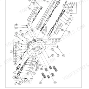
To troubleshoot relief valve pressures, first warm up the hydraulic oil until 3 lamps are lit on the temperature monitor. Install a pressure gauge in the pressure tap, start the engine, and engage the control for the circuit being tested. Adjustments are made at the main control valve; for example, the main relief valve setting is 4,200–4,500 psi (295–305 kgf/cm²). p. 88
How do you fix LS-2700 pump destroking and engine-load control problems?
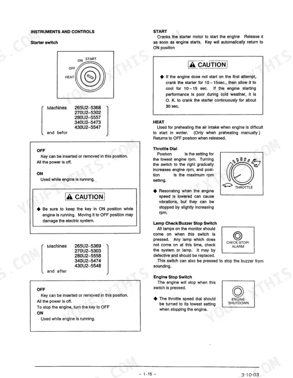
If the pump output does not increase even after selecting S or H modes, check the mode select switch. If the throttle speed dial malfunctions, you can use the Redundant (Backup) switch at the right console box. Placing this switch in the ON position fixes the load mode at S and allows the use of the MANUAL THROTTLE switch to control engine rpm. p. 40
What are the fuel filter and water separator element replacement specs for the Link-Belt LS-2700?
The fuel filter element should be replaced every 500 hours. Additionally, you must drain water and deposits from the fuel tank and water separator every 50 hours. When replacing the fuel filter, turn it counterclockwise for removal and bleed air from the system using the priming pump until no bubbles are visible. p. 76
What is the correct fan belt tension for the LS-2700?
The standard bending for the fan belt is 0.4 inches (10 mm) when pushed with a force of about 22 lb (10 kg) at a point between the generator and the water pump. If the belt is replaced, run the engine for about 1 hour and then recheck the tension. p. 77
What is the hydraulic oil tank capacity on the Link-Belt LS-2700 and what oil type is recommended?
The hydraulic oil tank capacity is 170 liters (44.7 gal). The recommended oil is an anti-wear type hydraulic oil, specifically ISO GRADE 46 or ISO GRADE 32 depending on ambient temperature. p. 98
How quickly can I access this Link-Belt LS-2700 manual after buying?
You get a 106-page searchable PDF that downloads instantly after checkout. Open it on your laptop, tablet, or phone, and bring it right to the shop floor.
Am I able to print pages from this Link-Belt LS-2700 manual?
Yes. Many mechanics print the section they need for their own shop and bring it to the bench.



Reviews
There are no reviews yet.