
Starting, travelling, transporting and greasing the Link-Belt 225 Spin Ace hydraulic crawler excavator are set out in this 158-page operator manual, OEM ID 1208, for the standard and Tier III builds. Lubrication, filters and fluids fill the largest share of this 225 Spin ACE Tier III operator manual PDF, with grease charts for machines with and without a dozer blade, hourmeter-based daily inspections, capacities and swing and travel reduction gear service. Pattern C and D lever layouts sit in the controls chapter, while later chapters cover rubber and steel tracks, idlers, fuses, lifting capacities and working range. Set steel track tension to 280 to 300 mm and rubber to 260 to 280 mm, then torque the track shoe bolts to 267 to 312 Nm. Loose track on your undercarriage is a slow, filthy job to correct twice. With bookmarks and a text layer, the 6 micron return filter rating is one search away, so you order the right filter first time.
What's Inside This Link-Belt 225 Spin Ace Tier III Operator Manual
| System | Pages | Key Topics |
|---|---|---|
| General Information | 1-12 | To the Owner, Excavator Components, Identification Numbers |
| Safety, Decals, and Hand Signals | 13-32 | Safety Rules, Safety Area, Utility Safety, Operator Precautions, Decals, Hand Signals |
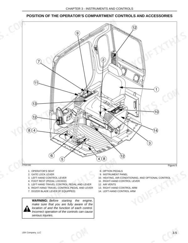
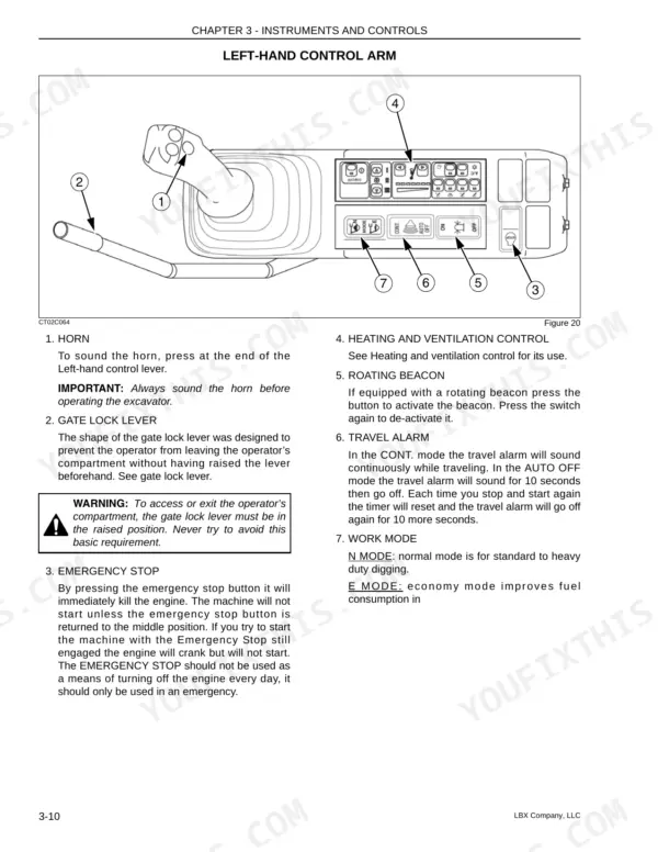
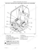
| Instruments and Controls | 33-60 | Cab Door, Steps and Access Handles, Position of the Operator’s Compartment Controls and Accessories, Right-Hand Control Arm, Instrument Panel, Left-Hand Control Arm, Heating |
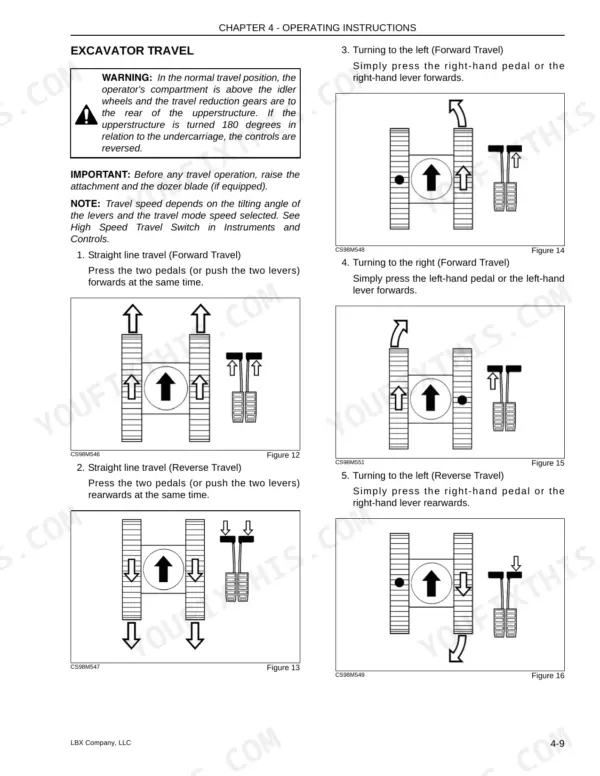
| Operating Instructions | 61-82 | Before Operating the Excavator, Operating the Excavator, Run-In Period, Starting the Engine, Bringing the Excavator Up to Operating Temperature, Engine Operation |
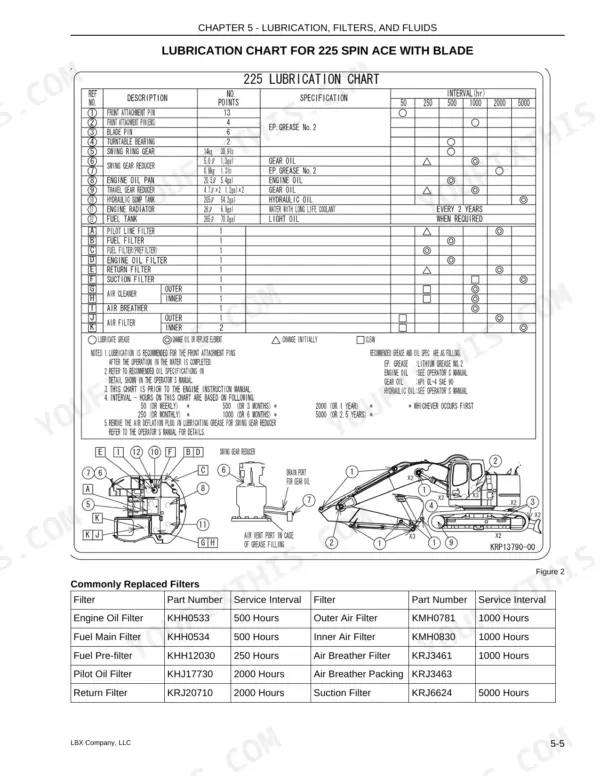
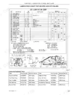
| Lubrication, Filters, and Fluids | 83-116 | Servicing Instructions, Daily Inspections, Hourmeter, Lubrication Chart for 225 Spin Ace with Blade, Lubrication Chart for 225 Spin Ace Without Blade, Fluids and Lubricants |
| Maintenance and Adjustments | 117-132 | Tracks, Checking the Condition of Rubber Tracks, Replacing the Rubber Tracks, Track Rollers and Idler Wheels, Radiator and Oil Cooler, Fan and Alternator Drive Belt |
| Electrical | 133-140 | Fuses, Battery, Connecting One or Two Booster Batteries, Alternator, Starter Motor, Replacing a Bulb, Working Lights |
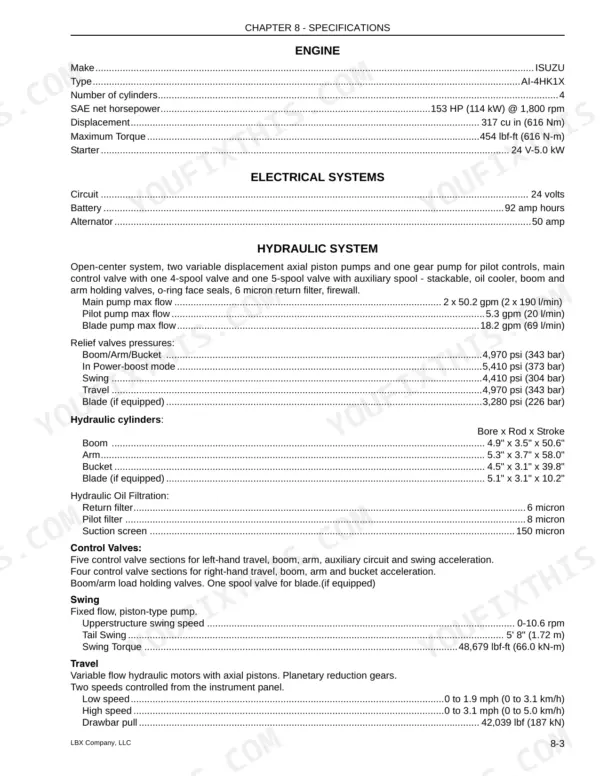
| Specifications | 141-156 | Engine, Electrical Systems, Hydraulic System, Undercarriage, Capacity of Systems and Components, Weights, Boom, Arms |
Quick Reference Specifications
| Specification | Value | Page |
|---|---|---|
| Return filter | 6 micron | p. 143 |
| Track Tension Value (Rubber tracks) | 11.0 - 11.8 in. (260 - 280 mm) | p. 121 |
| Track Tension Value (Steel tracks) | 10.2 - 11.0 in. (280 - 300 mm) | p. 121 |
| Tightening torque of the track shoe bolts | 267 to 312 Nm (196 to 230 ft lb) | p. 121 |
| Hydraulic pump torque setting | 49-55 lbf-ft (67-74 Nm) for M10, 152-167 lbf-ft (206-226 Nm) for M12 | p. 132 |
| Control valve torque setting | 197-230 lbf-ft (267-312 Nm) | p. 132 |
| Pilot filter | 8 micron | p. 143 |
| Main pump max flow | 2 x 50.2 gpm (2 x 190 l/min) | p. 143 |
| Pilot pump max flow | 5.3 gpm (20 l/min) | p. 143 |
| Engine Oil Capacity | 6.10 gal (23.1 liters) | p. 91 |
| Fuel Tank Capacity | 70.01 gal (265 liters) | p. 91 |
| Hydraulic System Total Capacity | 54.16 gal (205 liters) | p. 91 |
Link-Belt 225 Spin Ace Tier III Common Problems This Manual Covers
Link-Belt 225 Spin Ace overheating indicator lamp or engine oil pressure indicator lamp lit while running
Check the engine oil level first; engine oil capacity is 6.10 gal (23.1 liters) per page 91, so a low reading is not a small top-up. For the overheating lamp, clean the radiator and oil cooler and inspect the fan and alternator drive belt. If either lamp stays lit, shut down and find the cause.
Manual Section: Engine Troubleshooting (Overheating, Oil Pressure)Engine cranks but will not start after the fuel tank runs dry or a fuel filter change
Bleed air from the fuel system before you keep cranking and cook the starter. Keep the 70.01 gal (265 liters) tank listed on page 91 from running low. Replace the fuel main filter on the 500 hour interval shown on page 87, and bleed the system again after every filter change.
Manual Section: Fuel System Air BleedHydraulic pump, attachment cylinders or swing reduction gear holding air after hydraulic oil or filter service
Release pressure in the hydraulic system before opening anything. Then bleed air from the hydraulic pump, the attachment cylinders and the swing reduction gear. Fill the system properly; total hydraulic capacity is 54.16 gal (205 liters) per page 91. Replace the pilot oil filter on the 2000 hour interval listed on page 87.
Manual Section: Hydraulic Component BleedingAttachment cylinder rod appearance pointing to cylinder leakage during the daily walkaround inspection
Test the cylinder for leakage using the cylinder leakage check, then compare what you see on the rod against the rod appearance guidance in that section. Release pressure in the hydraulic system before loosening any fitting. Wipe the rod clean and check it again after a shift so you are reading fresh oil, not old grime.
Manual Section: Cylinder Leakage CheckTrack tension out of spec or track shoe bolts working loose on rubber or steel tracks
Measure track tension following page 121 and set it to the rubber or steel track value listed there. The two track types use different numbers, so do not mix them up. Torque the track shoe bolts to 196 to 230 ft lb (267 to 312 Nm). While you are down there, inspect the track rollers and idler wheels for damage.
Manual Section: Maintenance and Adjustments p. 121Engine will not crank with a weak battery charge state or a blown fuse
Check battery charge state and electrolyte level following the Electrical section starting on page 133. Before you swap any parts, check the fuse box against the function and amperage chart. If the battery is flat, connect one or two booster batteries using the booster procedure. Then inspect the alternator and starter motor.
Manual Section: Electrical p. 133Frequently Asked Questions
What causes hydraulic warning lights on a Link-Belt 225 Spin Ace?
Hydraulic warning lights, such as the overheating indicator lamp, illuminate when the hydraulic fluid temperature is abnormally high. If this occurs, you should bring the engine to idle mode and reduce the fluid temperature by checking and cleaning the radiator. p. 39
What are the hydraulic oil pressure specifications for a Link-Belt 225 Spin Ace?
The relief valve pressure for the Boom/Arm/Bucket is 4,970 psi (343 bar), while the Power-boost mode pressure is 5,410 psi (373 bar). The swing relief pressure is 4,410 psi (304 bar), and the travel relief pressure is 4,970 psi (343 bar). p. 143
What are the replacement specs for the hydraulic return and pilot filters on a Link-Belt 225 Spin Ace Tier III?
The pilot filter and return filter should be replaced every 2,000 hours, with an initial replacement required after the first 250 hours during the run-in period. p. 105
What is the engine oil capacity for the Link-Belt 225 Spin Ace?
The engine oil capacity for the Link-Belt 225 Spin Ace is 6.10 gallons (23.1 liters) when performing an oil change with a filter change. p. 96
What is the correct belt tension for the fan and alternator drive belt?
The tension slack for the fan and alternator drive belt should be between 0.39 and 0.59 inches (10 to 15 mm) when applying approximately 20 lbs of pressure to the center of the belt. p. 126
Is this Link-Belt 225 Spin Ace manual a download or a disc?
A single searchable PDF file of 158 pages, downloadable right after payment. Nothing ships, nothing waits in the mail.
Can I print pages of this Link-Belt 225 Spin Ace manual for my own shop?
Yes. Print the sections you need to take out to the shop for your own use. Standard letter or A4 paper works.



Reviews
There are no reviews yet.