
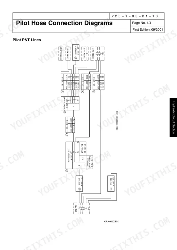
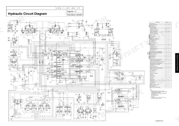
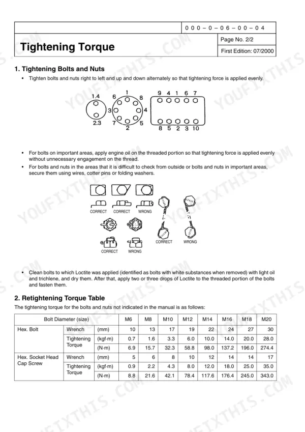
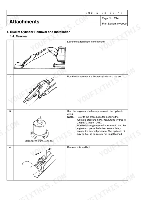
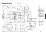
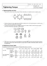
A travel motor weeping oil or a swing that drifts on a slope is the job this book was written for: an 811-page shop manual for the Link-Belt 225 Spin Ace and SH225X-3 hydraulic excavator, OEM ID 1113. Hydraulic circuit diagrams, electric circuit diagrams, pilot hose connection drawings and harness layouts close out this SH225X-3 shop manual PDF, so you can trace a pilot signal from the remote control valve to the spool it shifts. The travel unit alone takes up more than a sixth of the book, and the swing unit, control valve, cylinders and remote control valve each get their own teardown and assembly chapters, most with troubleshooting built in. Fill the hydraulic system to 205 L with 120 L in the tank, then torque M12 hex bolts to 58.8 N·m (6.0 kgf·m). One missing torque figure can park a half-built final drive. Bookmarked chapters and a live text layer put the section your job needs two clicks away.
What's Inside This Link-Belt 225 Spin Ace, SH225X-3 Manual
| System | Pages | Key Topics |
|---|---|---|
| About This Shop Manual | 5-32 | Safety, Introduction, Using Technical Information, Tightening Torque, Numerical Conversion Table |
| Service Manual | 33-194 | Specifications, Equipment Configuration |
| Troubleshooting | 195-241 | Problem Symptoms, Inspection Prior to Troubleshooting, Troubleshooting Procedures |
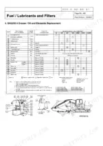
| Specification Add-On Items | 242-265 | Major Equipment Specifications, Fuel and Lubricants |
| Performances | 266-278 | Main Body Weight, New Machine Performance, Lifting Capacity |
| Disassembling and Maintenance Instructions for the Main Body | 279-322 | Maintenance Instructions, Lower Mechanism, Upper Mechanism |
| Disassembling and Maintenance Instructions for Major Parts | 323-392 | Take-Up Roller, Upper Roller, Lower Roller, Grease Cylinder, Rotating Joint |
| Hydraulic Pump | 393-428 | Piston Internal Structure, Disassembly, Assembly, Maintenance Criteria, Troubleshooting |
| Travel Unit | 429-571 | Handling Instructions, Safety Precautions, Disassembly, Assembly, Troubleshooting |
| Swing Unit | 572-616 | Component Configuration, Hydraulic Motor Structure, Disassembly, Assembly, Relief Assembly |
| Control Valve | 617-652 | Disassembly, Assembly, Relief Valve, Overload Relief Valve, Parts List |
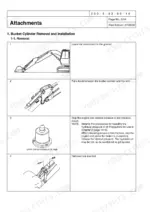
| Cylinder | 653-714 | Structural Drawings, Maintenance Instructions, Error Diagnosis, Disassembly, Assembly |
| Remote Control Valve | 715-787 | Operation, Maintenance Procedures, Disassembly, Assembly, Troubleshooting |
| Solenoid Valve | 788-809 | Theory of Operation, Maintenance, Troubleshooting, Dimensional Outline Drawings |
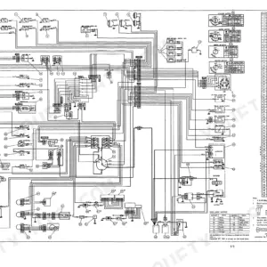
| Schematics | 810-811 | Hydraulic Circuit Diagrams, Electric Circuit Diagrams, Pilot Hose Connection Diagrams, Harness Diagrams |
Quick Reference Specifications
| Specification | Value | Page |
|---|---|---|
| Hex. Bolt Tightening Torque (M6) | 0.7 kgf·m (6.9 N·m) | p. 29 |
| Hex. Bolt Tightening Torque (M8) | 1.6 kgf·m (15.7 N·m) | p. 29 |
| Hydraulic oil capacity | 205 L | p. 39 |
| Hydraulic oil tank capacity | 120 L | p. 39 |
| Hydraulic sump tank capacity | 200 L | p. 53 |
| Main pump rated working pressure | 34.3 MPa | p. 52 |
| Main pump maximum working pressure | 37.2 MPa | p. 52 |
| Travel unit working pressure | 34.3 MPa | p. 46 |
| Travel unit working flow | 212.2 L/min | p. 46 |
| Swing unit brake torque | 856.2 N·m or above | p. 48 |
| Swing unit brake release pressure | min. 3.2 MPa | p. 48 |
| Boom Cylinder Right/Left Dry weight | 200 kg | p. 58 |
Link-Belt 225 Spin Ace, SH225X-3 Common Problems This Manual Covers
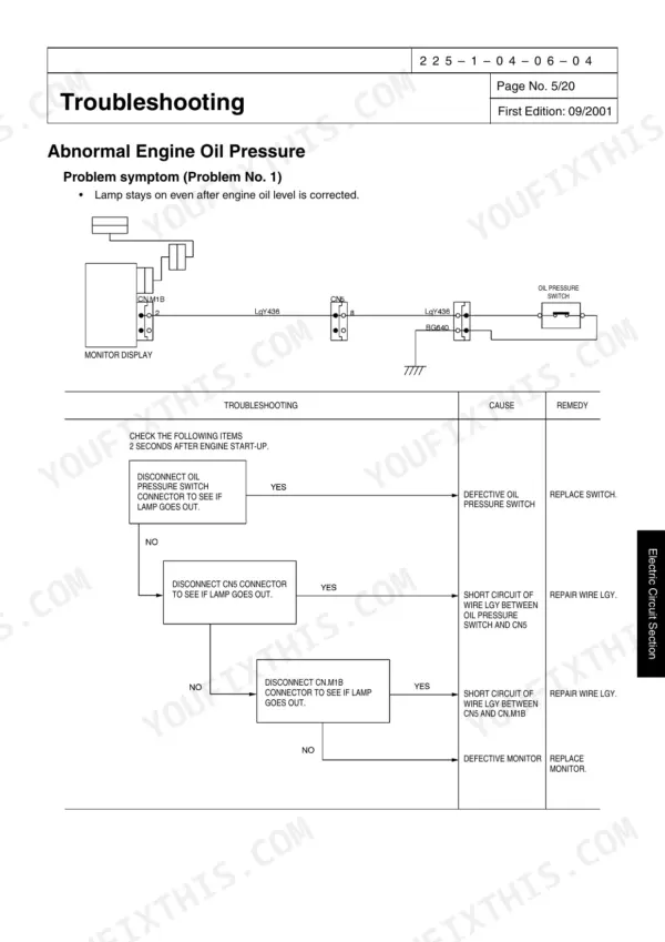
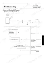
Link-Belt 225 Spin Ace and SH225X-3 engine oil pressure warning lamp stays on after oil level is corrected
Verify the engine oil level with the engine stopped, then work through the Abnormal Engine Oil Pressure flow on page 199 in order, confirming each check before moving on. If the level is correct and the lamp stays lit, treat it as a real fault, not a lamp quirk, and keep the machine parked until it is traced.
Manual Section: Abnormal Engine Oil Pressure p. 199Overheat warning lamp stays on even though temperatures are within the normal range
Check actual operating temperature first so you know whether you are chasing heat or a false lamp. If temperatures are within the normal range and the lamp stays lit, follow the Overheat procedure starting on page 201 and clear each step in sequence. Verify the lamp goes out at operating temperature before you release the machine to the crew.
Manual Section: Overheat p. 201Engine electrical system fault lamp stays on with governor servo, rack sensor or throttle sensor error codes
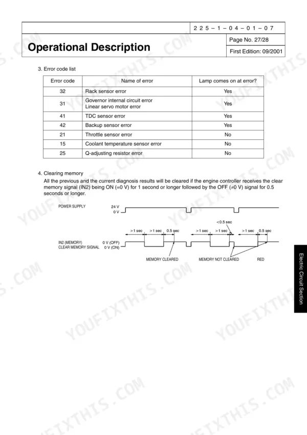
Verify which error code is displayed before touching anything, and write it down. Follow the Engine Electrical System Faults procedure on page 203, then match the code to the Engine Diagnosis listing for codes 31, 32, 41, 42, 21, 15 and 25, which covers governor servo errors, the rack, TDC, backup, throttle and coolant temperature sensors, and the Q-adjusting resistor.
Manual Section: Engine Electrical System Faults p. 203Travel motor does not rotate, runs at insufficient speed or stops while operating
Test travel circuit pressure at the motor before condemning it; the SH225X-3 travel unit working pressure is 34.3 MPa on page 46. If pressure is low, inspect the travel motor relief valve and counter balance valve next, since both carry their own does-not-rotate and slow-rotation checks in the Travel Unit troubleshooting.
Manual Section: Piston Motor TroubleshootingTravel motor rotates while parked, will not develop driving power, or parking brake runs abnormally hot
Check whether the motor creeps under external load with the machine stopped, or whether the brake runs hot. Then work through the Parking brake troubleshooting table on page 498 in order, from worn disks to distorted disk faces, before you split the motor housing.
Manual Section: Parking Brake Troubleshooting p. 498Travel reduction gear does not rotate, makes abnormal noise, runs hot, or leaks oil
Check the reduction gear oil level and condition before anything else, and pull the hour meter history. Verify the oil was changed at the 100 to 250 hour initial interval and every 1000 to 1500 hours after that, per page 493. Then work through the Reduction Gear Troubleshooting checks for noise, heat and leakage in order.
Manual Section: Travel Unit p. 493Frequently Asked Questions
How do I reset the error codes on the Link-Belt 225 Spin Ace?
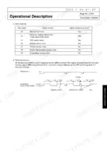
All previous and current diagnosis results can be cleared if the engine controller receives the clear memory signal (IN2) being ON (=0 V) for 1 second or longer, followed by an OFF (≠0 V) signal for 0.5 seconds or longer. p. 188
What are the torque specifications for the main relief valve on the Link-Belt 225 Spin Ace?
The tightening torque for the main relief valve is 78 to 88 N·m. p. 625
How do I adjust the hydraulic pressure on the Link-Belt 225 Spin Ace?
To adjust the main relief pressure, loosen the standard lock nut and adjust the pressure using the adjusting screw. For power boost pressure, loosen the power boost lock nut and adjust with the power boost adjusting screw. Page 233 sets the standard pressure at 34.3 ± 0.5 MPa and power boost at 37.3 ± 0.5 MPa. p. 233
What is the replacement interval for the engine oil filter on the Link-Belt 225 Spin Ace?
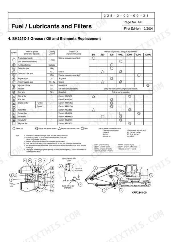
The engine oil filter (full flow) should be replaced every 500 hours. p. 262
What is the correct hydraulic oil capacity for the Link-Belt 225 Spin Ace?
The hydraulic oil tank capacity is 120 L, and the total hydraulic oil capacity is 205 L. p. 39
Is this Link-Belt 225 Spin Ace manual a download or a disc?
A single searchable PDF file of 811 pages, downloadable right after payment. Nothing ships, nothing waits in the mail.
Is this Link-Belt 225 Spin Ace Shop Manual printable?
Yes. Many mechanics print the section they need for their own shop and bring it to the bench.


Reviews
There are no reviews yet.