
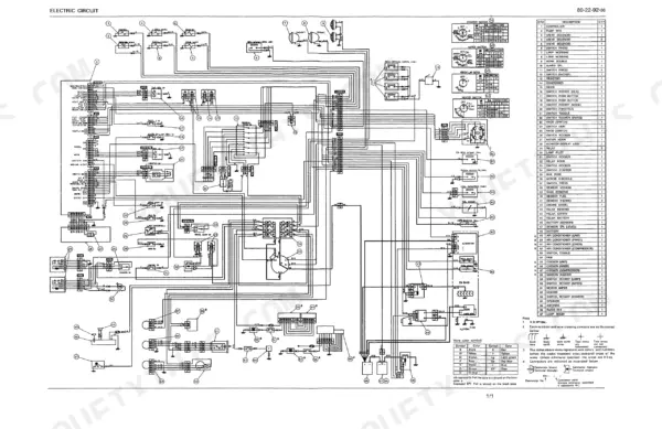
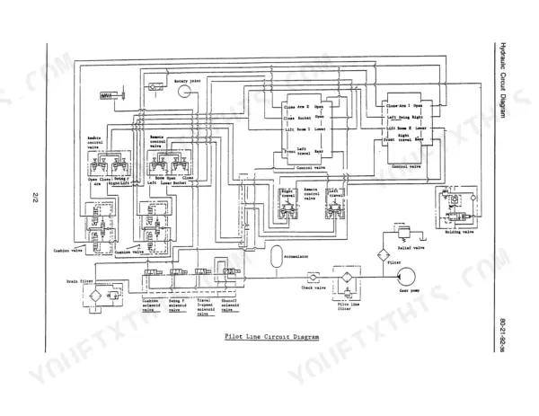
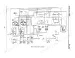
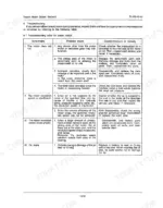
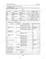
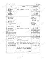
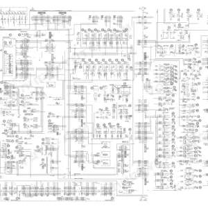
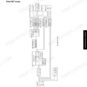
Getting a travel motor, swing motor or main pump rebuild right the first time on an older LS-series hydraulic excavator is what 339 pages of factory data buy you in this Link-Belt LS-4300 shop manual PDF, Book No. WEL4305-0E. Hydraulic and electric circuit diagrams near the front trace the pilot line, holding valve, controller, valve solenoids and throttle motor, while the travel motor, swing motor and hydraulic pump chapters fill more than half the book with disassembly, reassembly and troubleshooting. Pilot valve, control valve, rotating joint and hydraulic cylinder work follow, ending on undercarriage wear limits for the sprocket, front idler, rollers and grouser shoes. Set the pilot circuit at 45 kgf/cm² and the swing brake valve at 280 ± 10 kgf/cm². A drifting swing with no brake figure eats a shift. Bookmarked by chapter with a live text layer, this copy is bought once and stays yours for the life of your machine.
What's Inside This Link-Belt LS-4300CII Manual
| System | Pages | Key Topics |
|---|---|---|
| Caution for Inspection and Maintenance & Basic Rules | 5-12 | Caution for Inspection and Maintenance, Basic Rules, Fire Prevention, Machine Inspection, Maintenance Safety, Tool Usage, Heavy Object Handling, General Rules for Disassembling, General Rules for Reassembling, Handling of the Interchangeable Parts |
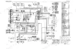
| Hydraulic Circuit | 13-14 | Travel Motor, Bucket Cylinder, Boom Cylinder, Hydraulic Pump, Pilot Line Circuit, Holding Valve |
| Electric Circuit | 15-16 | Controller, Valve Solenoid, Pressure Switch, Throttle Motor, Battery, Sensor |
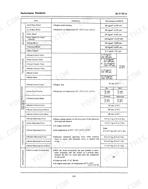
| Performance Standards & Measuring Pressure | 17-30 | Performance Standards, Measuring Pressure, Oil Stopper for Suction Strainer, Setting Pressure, Valve Spool Stroke, Control Lever Operating Force, Swing Performance, Travel Performance, Cylinder Performance, Accumulator Gas Pressure Verification, Suction Strainer, Oil Stopper, Hydraulic Pump, Suction Lines |
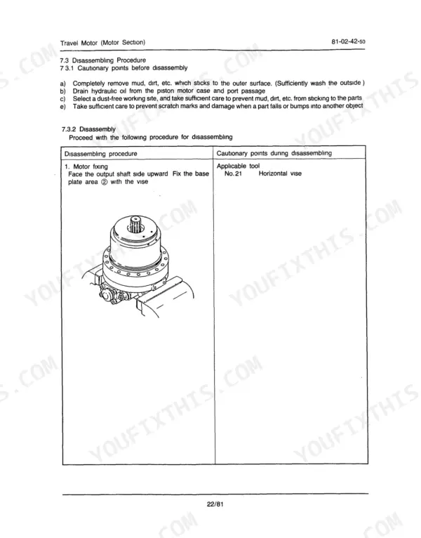
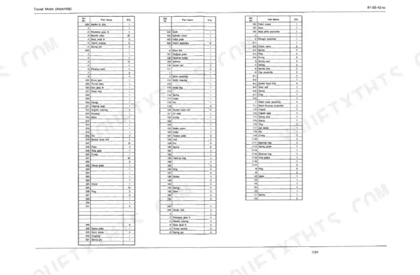
| Travel Motor, Rollers & Recoil Spring | 31-130 | Travel Motor, Traction Drive Assembly, Upper Roller, Lower Roller, Recoil Spring, Cautionary Points for Operation, Troubleshooting, Traction Motor, Drive Sprocket, Mounting Bolts, Washer, Mounting Bolt, Spacer, Track Roller, Oil Level Plug, Structural Diagram, Grease Cylinder, Piston Rod |
| Swing Motor, Turntable Bearing & Engine Mounting | 131-182 | Swing Motor, Swing Motor Assembly, Turntable Bearing, Engine Mounting, Cautionary Points for Operation, Troubleshooting, Disassembling Procedure, Reassembling Procedure, Motor Section, Reduction Gear Section, Maintenance Procedure, Grease Application, Bolt Tightening, Cushion Rubber, Hydraulic Pump Side, Fan Side |
| Hydraulic Pump, Pump Installation & Rotating Joint | 183-246 | Hydraulic Pump, Pump Installation, Rotating Joint, Details of Parts, Tools and Jigs, Disassembly, Reassembly, Troubleshooting, Pump Casing, Suction Line, Bolt Tightening, Air Bleeding, Rotating Joint Assembly, Disassembly Procedure, Seal Replacement, Assembly Procedure, Special Jig |
| Pilot Valve | 247-270 | Maintenance, Disassembly, Reassembly |
| Control Valve | 271-292 | Cautions in Handling the Control Valve, Control Valve Disassembly and Reassembly, Troubleshooting |
| Hydraulic Cylinder | 293-308 | Disassembly and Assembly Procedures, Maintenance Standard, Reassembling Procedure |
| Monitor | 309-324 | Function and Construction Description, Disassembly and Reassembly |
| Weight of Components, Maintenance Standards & Conversion Table | 325-339 | Weight of Components, Maintenance Standards, Conversion Table, Weight Distribution, Individual Parts Weight, Shipping Weight, Drive Sprocket, Front Idler, Upper Roller, Lower Roller, Grouser Shoes, Swing Equipment, Attachment, Weight, Length, Capacity, Pressure, Torque, Temperature |
Quick Reference Specifications
| Specification | Value | Page |
|---|---|---|
| Pilot circuit setting pressure | 45 kgf/cm² | p. 25 |
| Swing brake valve setting pressure | 280 ± 10 kgf/cm² | p. 27 |
| Travel motor assembly mounting bolts (M20 x 24 pieces) tightening torque | 53.1 to 62.0 kg-m (384.1 to 448.4 ft-lb) | p. 36 |
| Pilot pump relief valve adjustment screw pressure per turn | 14 kgf/cm² | p. 25 |
| Swing brake valve adjustment screw pressure per turn | 24 kgf/cm² | p. 27 |
| Travel motor assembly mounting bolts (M24 x 18 pieces) tightening torque | 91.8 to 107.2 kg-m (664.0 to 775.4 ft-lb) | p. 36 |
| Filter filtering degree | 10 μ (nominal) or less | p. 44 |
| Double pump working pressure A1, A2 | MAX 345 x 2 kgf/cm² | p. 183 |
| Double pump input shaft rotation speed | 2000 rpm | p. 183 |
| Pilot pump working pressure A3 | 40 kgf/cm² | p. 183 |
| Adjusting screw tightening torque | 500±35 kgf·cm (36.2 ft lb) | p. 250 |
| Travel Motor Lubricant Capacity | 8.5 liters | p. 36 |
Link-Belt LS-4300CII Common Problems This Manual Covers
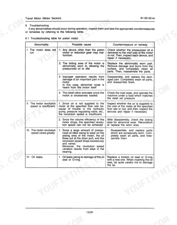
Link-Belt LS-4300 travel motor does not run, revolution speed is insufficient, or revolution speed varies
Check the piston motor against the troubleshooting steps before pulling it. Measure drain pressure in the piston motor case against 2 kg/cm² (28.4 psi) ordinary and 5 kg/cm² (71.1 psi) instantaneous maximum from page 45. Verify the motor case is filled with 400 cc (13.2 oz) of hydraulic oil, per page 46.
Manual Section: Travel Motor Piston Motor TroubleshootingTravel motor does not stop or stops slowly, with shock when travel is stopped
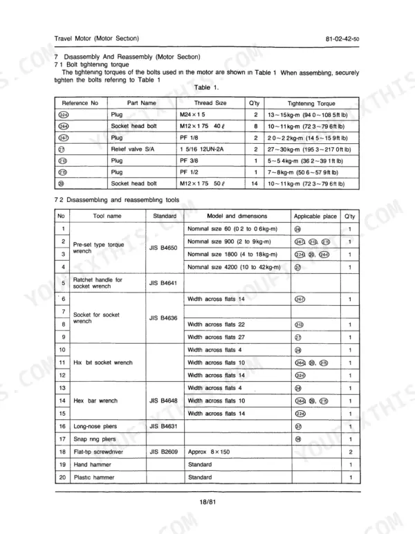
Measure the travel brake valve relief setting following page 28 and compare it against 375 ± 10 kgf/cm². Check the relief valve before suspecting the double counterbalance valve. When reinstalling the relief valve S/A, torque it to 27~30 kg-m (195.3~217.0 ft lb) as listed on page 53.
Manual Section: Travel Motor Relief Valve TroubleshootingSwing motor revolution speed is insufficient, brake torque is insufficient, or slip rate is high
Measure swing brake valve setting pressure following page 27 against 280 ± 10 kgf/cm²; each turn of the adjustment screw shifts it 24 kgf/cm². If pressure checks good, pull the motor and measure friction plate thickness against the page 161 values (4.0 mm, recommended 3.6 mm), plus piston to bore clearance (0.032 mm, recommended 0.062 mm).
Manual Section: Swing Motor p. 131Hydraulic pump has insufficient flow rate, no pressure rise, or overheating during operation
Verify pump output against page 183: maximum 345 x 2 kgf/cm² working pressure and 205 x 2 l/min delivery at 2000 rpm input speed. Before opening the pump or suction lines, make the oil stopper for the suction strainer described on page 29. After any pump removal, bleed air following the installation steps on page 241.
Manual Section: Hydraulic Pump p. 183Pilot circuit pressure reads below setting pressure on the gauge during the pressure check
Measure pilot circuit pressure following the procedure on page 25 and compare it against 45 kgf/cm². Adjust the pilot pump relief valve screw to correct it; each turn changes pressure 14 kgf/cm². If it will not come up, check the pilot pump section rating (A3, 40 kgf/cm² working pressure) on page 183.
Manual Section: Measuring Pressure p. 25Control valve spool sticking, or negative load cannot be held and drops
Remove and inspect the sticking spool and its bore following the disassembly steps in the control valve section starting on page 271, observing the handling cautions there. Verify relief valve pressure before condemning the valve body, then reassemble following the same section.
Manual Section: Control Valve p. 271Frequently Asked Questions
How do I test pilot pressure on a Link-Belt LS-4300 CII?
To test pilot pressure, first position the attachment on the ground and stop the engine. Place the starter key and control switch in the ON position, then move the operation levers ten times in all four directions to relieve pressure. Slowly loosen the air breather on the hydraulic oil tank to bleed air, then install the pressure gauge at the pilot pump relief valve as shown in Fig 2 on page 25. p. 25
What are the hydraulic pump pressure specifications for the LS-4300?
The main relief pressure for the R H and L H main relief valves is 320 kg/cm² (4,550 psi). The port relief pressure is 340 kg/cm² (4,835 psi), and the pilot control pressure is 31.7 kg/cm² (751 psi). p. 17
What is the lubricant capacity for the travel motor reduction gear on the Link-Belt LS-4300?
The specified lubricant capacity for the travel motor reduction gear is 8.5 liters (2.24 gallons). p. 36
What is the tightening torque for the cylinder head bolts on the Link-Belt LS-4300 hydraulic cylinders?
The tightening torque for the cylinder head bolts depends on the cylinder type: 61.5 ± 11.5 kg-m (445 ± 83 ft.lb) for the Boom (M22 x 2.5), 77.9 ± 14.7 kg-m (563 ± 106 ft.lb) for the Arm (M24 x 3), and 61.5 ± 11.5 kg-m (445 ± 83 ft.lb) for the Bucket (M22 x 2.5). p. 307
What is the recommended replacement interval for the travel motor lubricant on the Link-Belt LS-4300?
The initial replacement of the travel motor lubricant should be performed after 100 to 250 hours of operation. Subsequent replacements should occur every 1,000 to 1,500 hours. p. 34
What do I get after purchasing this Link-Belt LS-4300 manual?
All 339 pages arrive as one searchable PDF at checkout. Read it at the desk, then take the phone out to the machine.
Can I print pages of this Link-Belt LS-4300 manual for my own shop?
Yes. Many buyers print one chapter at a time for their own shop and keep the rest on a tablet.


Reviews
There are no reviews yet.