
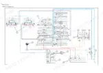
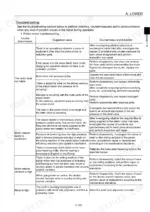
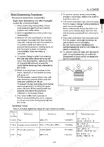
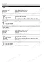
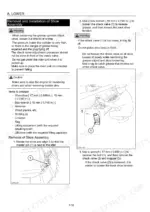
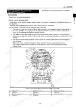
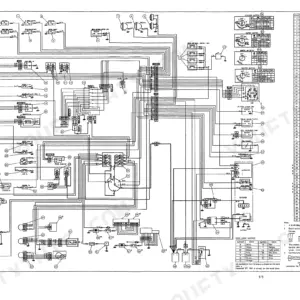
Pulling a travel motor or rebuilding a lower roller goes smoother with all 286 pages of this Link-Belt 235X3 service manual PDF (OEM ID 15955044-0) open beside you. It's written for the X3 generation hydraulic excavator in both standard and Blade versions. Hydraulic circuit explanations fill nearly a third of the book, tracing flow through the travel, swing, boom, arm, bucket and negative control circuits before moving into breaker, double-acting and multi-purpose option circuits. Undercarriage work gets the same attention, from track shoe and sprocket removal to roller, take-up roller and center joint rebuilds built around jig dimension diagrams, and the travel motor teardown ends in its own troubleshooting chart. Set main relief at 34.3 MPa (4974 psi), and expect the travel motor to switch to second speed at 25.8 MPa (3742 psi). A travel motor that won't shift up can cost a whole shift. Bookmarks take you to the section you need in one click, and the text layer finds a term like drain volume instantly.
What's Inside This Link-Belt 235X3 Manual
| System | Pages | Key Topics |
|---|---|---|
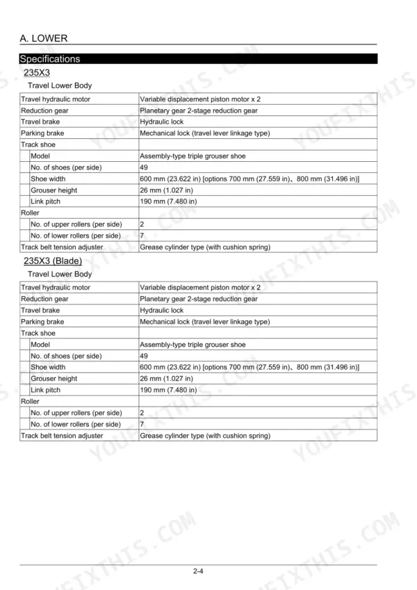
| Specifications | 6 | Variable Displacement Piston Motor, Planetary Gear 2-Stage Reduction Gear, Grease Cylinder Type (with Cushion Spring) |
| Main Equipment Table | 7-10 | 235X3, Automatic 2-Speed Switchover with Parking Brake, Relief Valve Set Pressure, Mounting Length of Spring |
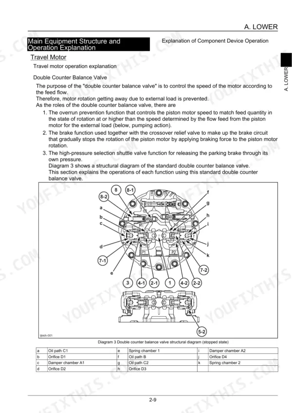
| Main Equipment Structure and Operation Explanation | 11-25 | Travel Motor Operation, Crossover Relief Valve, Automatic 2-Speed Switchover Mechanism |
| Port Diagram | 26 | Travel Motor, Center Joint |
| Basic Functions | 27-30 | Travel Speed Selection, Travel Alarm |
| Removal and Installation of Track | 31 | Grease Cylinder Check Valve, Track Shoe Tension, Shoe Assembly |
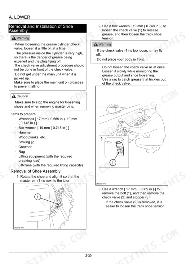
| Removal and Installation of Shoe Assembly | 32-35 | Removal of Shoe Assembly, Installation of Shoe Assembly, Track Shoe Tension, Striking Rod, S-Pin, Master Pin, Box Wrench |
| Removal and Installation of Shoe Plate | 36 | Removal of Shoe Plate, Installation of Shoe Plate, Tightening Torque |
| Removal and Installation of Roller | 37-55 | Removal and Installation of Upper Roller |
| Removal and Installation of the Sprocket | 56-57 | Removal of Sprocket, Installation of Sprocket, Air Bleeding, Striking Jig, Tightening Torque M16 |
| Removal and Installation of Take-Up Roller | 58-67 | Removal of Take-Up Roller, Installation of Take-Up Roller, Bushing Press-Fit Jig, Floating Seal Installation Jig, Fill Engine Oil |
| Removal and Installation of Grease Cylinder | 68-69 | Removal of Grease Cylinder, Installation of Grease Cylinder, Track Guard, Grease Cylinder Installation Bolt Tightening |
| Assembly and Disassembly of Tension Shock Absorber | 70-73 | Configuration Diagram, Dimension Diagram, Jig Dimension Diagram, Disassembly Procedures, Assembly Procedures, Dust Seal Press-Fit Jig, U-Packing, Check Valve Tightening Torque |
| Removal and Installation of Center Joint | 74-77 | Removal of Center Joint, Installation of Center Joint, Vacuum Pump, Pilot Hoses |
| Assembly and Disassembly of Center Joint | 78-84 | Configuration Diagram, Dimension Diagram, Jig Dimension Diagram, Disassembly Procedures, Assembly Procedures, Axle Removal Jig, Packing Rings, V-Ring |
| Removal and Installation of Travel Motor | 85-89 | Removal of Travel Motor, Installation of Travel Motor, Air Bleeding, High-Pressure Hoses, Tightening Torque M16 |
| Assembly and Disassembly of Travel Motor | 90-136 | Tools for Assembly and Disassembly, Motor Disassembly Procedures, Motor Assembly Procedures, Troubleshooting, Structural Diagram |
| Maintenance Standards | 137-145 | Drive Sprocket, Take-Up Roller, Upper Roller, Lower Roller, Track Shoe, Inspection Gauge |
| Pressure Measurement and Adjustment Procedures | 146 | Main Pressure Measurement |
| Drain Volume Measurement Procedures | 147-148 | Preparations, Travel Motor Drain Volume Measurement |
| Air Bleed Procedure | 149-150 | Hydraulic Pump Air Bleeding, Cylinder Air Bleeding, Swing Motor Air Bleeding, Travel Motor Air Bleeding |
| Swing Unit and Counterweight | 151-197 | Swing Motor Specifications, Swing Unit Removal and Installation, Swing Motor Assembly and Disassembly, Counterweight Removal and Installation |
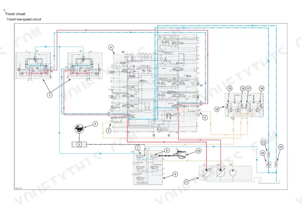
| Hydraulic Circuit Explanation (Standard Model) | 198-268 | Travel Circuit, Swing Circuit, Boom Circuit, Arm Circuit, Bucket Circuit, Negative Control Circuit |
| Option Circuits | 269-286 | Breaker Circuit, Double-Acting Circuit, Multi-Purpose Circuit, 2nd Option Circuit, Hydraulic Rotation Fork |
Quick Reference Specifications
| Specification | Value | Page |
|---|---|---|
| Travel Unit Operating pressure | 34.3 MPa (4975.341 psi) | p. 7 |
| Travel Unit Operating flow | 234.0 L/min (61.818 gpm) | p. 7 |
| 235X3 Track shoe width | 600 mm (23.622 in) | p. 6 |
| 235X3 Grouser height | 26 mm (1.027 in) | p. 6 |
| Main Relief Valve (Standard) Pressure Setting | 34.3 MPa / 343 bar / 4974 psi | p. 286 |
| Main Relief Valve (Boost) Pressure Setting | 36.8 MPa / 368 bar / 5337 psi | p. 286 |
| Boom Raising Port Secondary Relief Pressure Setting | 38.7 MPa / 387 bar / 5612 psi | p. 286 |
| Boom Lowering Port Secondary Relief Pressure Setting | 29.4 MPa / 294 bar / 4264 psi | p. 286 |
| Travel hydraulic motor operating pressure | 34.3 MPa | p. 7 |
| Center joint operating pressure (High-pressure passage) | 34.3 MPa | p. 8 |
| Shoe bolt tightening torque | 751 - 849 N·m | p. 36 |
| Upper roller bolt tightening torque | 521 - 608 N·m | p. 39 |
Link-Belt 235X3 Common Problems This Manual Covers
Link-Belt 235X3 travel motor does not rotate or rotation speed is insufficient while traveling
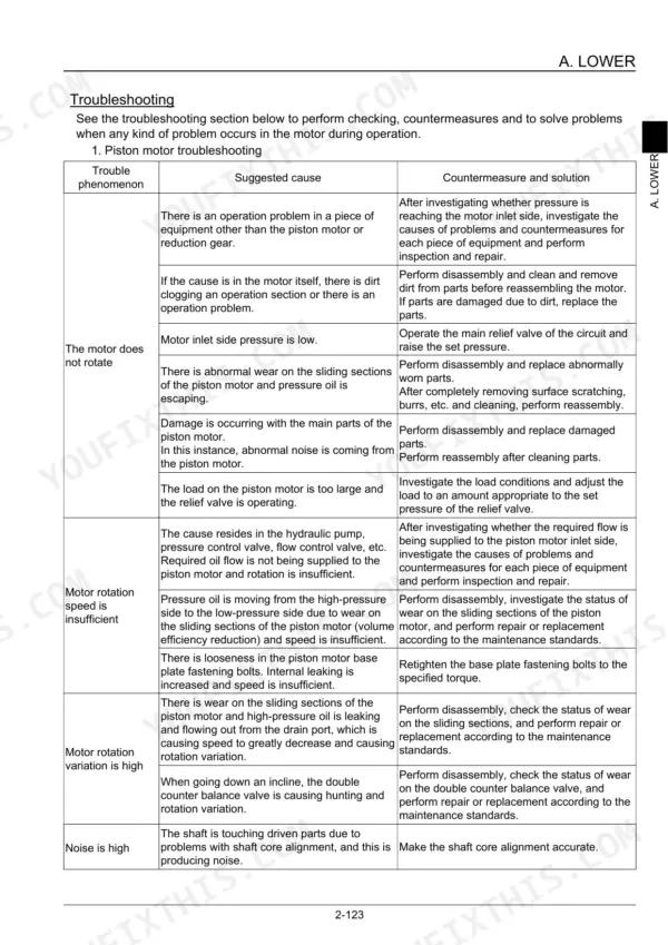
Measure main pressure following page 146 and confirm the 34.3 MPa set pressure before condemning the motor. Then run the travel motor drain volume measurement on page 147 to check the motor's internal condition. Work through the piston motor troubleshooting chart on page 125 before pulling the unit.
Manual Section: Piston motor troubleshooting p. 125Travel motor does not stop or stopping is slow, with high shock at stopping
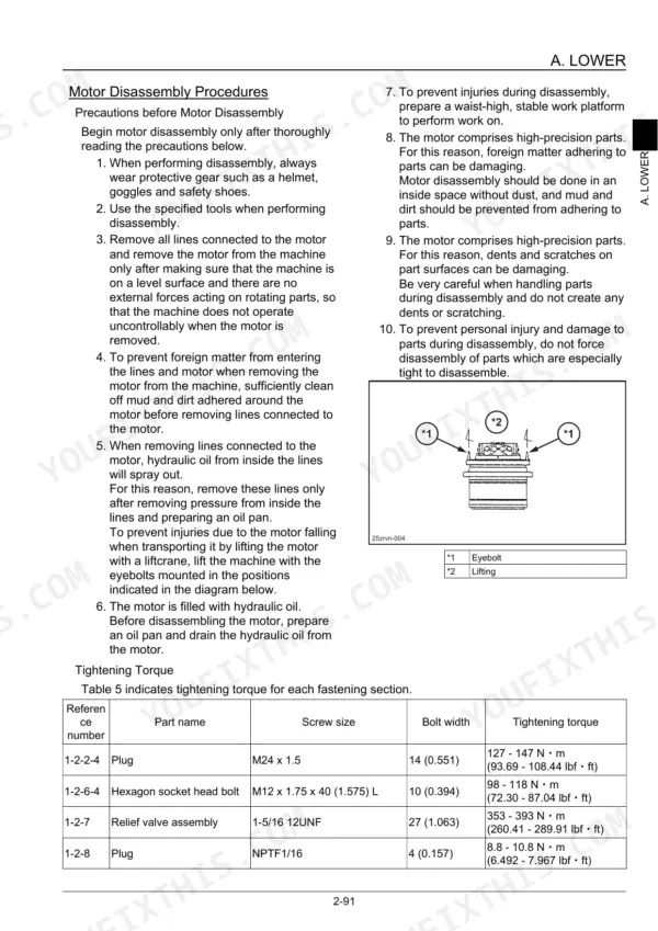
Check the travel relief valve against the 35.3 MPa at 40 L/min set pressure listed on page 7, then inspect the counter balance valve, which shows the same slow stop symptom. When refitting the relief valve assembly, torque it to 353 to 393 N·m per page 93.
Manual Section: Relief valve troubleshootingTravel motor parking brake lets motor rotate when stopped with external load applied
Verify the parking brake against the 25.1 kN·m minimum brake torque on page 7. If the motor still creeps or runs hot, strip the travel motor following the disassembly procedures from page 90 and inspect the brake section. Bleed air from the travel motor per page 149 after reassembly.
Manual Section: Parking brake troubleshootingTravel will not switch to high-speed, or drops to low-speed as hydraulic oil temperature increases
Check travel speed selection operation as described on page 27 first. Then verify the automatic 2-speed switchover pressure of 25.8 MPa from page 7 and check the center joint, whose pilot port is rated at 3.9 MPa on page 8. Work the 2-speed control function troubleshooting before replacing travel motor parts.
Manual Section: 2-speed control function section troubleshootingSwing motor does not rotate, has insufficient braking torque, or shows severe slipping
Check swing port secondary relief pressure against the 29.4 MPa setting on page 286, which matches the swing motor operating pressure on page 156. If pressure is correct, remove the swing unit and work through the swing motor teardown in the section starting page 151. Torque swing unit bolts to 539.4 to 629.6 N·m per page 173.
Manual Section: Swing Unit and Counterweight p. 151Track chain link pitch, track pins and bushings worn past usage limit
Measure the 4-link pitch following page 143: standard is 760 mm, usage limit is 774.9 mm. Check track pins against the 35.5 mm limit and shoe plates against the 30 mm limit. When refitting shoes, torque shoe bolts to 751 to 849 N·m per page 36.
Manual Section: Maintenance Standards p. 143Frequently Asked Questions
What is the tightening torque for the travel motor installation bolts on a Link-Belt 235X3?
The tightening torque for the travel motor installation bolts (M16) is 267 - 312 N·m (196.96 - 230.16 lbf·ft). p. 88
How much gear oil is in the Link-Belt 235X3 travel motor reduction gear from the factory?
When motors are shipped from the plant, they are filled with Nippon Oil Hypoid Gear Oil 90 to a stipulated volume of 5.0 L (1.32 gal). p. 123
What is the procedure for bleeding air from the travel motor?
After replacing hydraulic equipment, run the engine at low idle and remove the air bleed plug using an 8 mm hexagon wrench. Ensure oil oozes from the port, then tighten the plug and execute a slow travel operation, traveling forward and backward to bleed the air. p. 149
What is the tightening torque for the shoe plate bolts on a Link-Belt 235X3?
The tightening torque for the 4 shoe bolts is 751 - 849 N·m (554.00 - 626.30 lbf·ft). p. 36
What is the required oil fill amount for the Link-Belt 235X3 upper roller during assembly?
During the assembly of the upper roller, you must inject 50 - 55 cc of engine oil (Shell Rimula Oil #30) into the roller. p. 46
What exactly do I receive with this Link-Belt 235X3 Service Manual?
Delivery is instant: a 286-page searchable PDF is yours the second checkout clears. Laptop, tablet, or phone, all fine.
Can I print specific sections of this Link-Belt 235X3 Service Manual?
Yes. Print a single page or a chapter for your own shop use, on letter or A4.


Reviews
There are no reviews yet.